
Exercise sole

a technology of shoes and soles, applied in the field of shoes for exercise, can solve problems such as injury to wearers

Inactive Publication Date: 2005-07-28
WHATLEY IAN H
View PDF3 Cites 22 Cited by
  • Summary
  • Abstract
  • Description
  • Claims
  • Application Information

AI Technical Summary

Benefits of technology

The invention offers shoe soles that offer complete movement for the calf muscles during workouts, give smooth rolls at the front foot, align perfectly with where the body's weight is applied when leaping, and have an ideal size for training the calf muscles.

Problems solved by technology

The technical problem addressed in this patent is how to design a better sole for athletic footwear that can provide increased support and comfort while also improving performance during jumping, running, plyometric exercise, and power walking movements. Different designs have been created but each one needs improvement upon to achieve optimal results.

Method used


Image

  • Exercise sole
  • Exercise sole
  • Exercise sole

Examples


Embodiment Construction

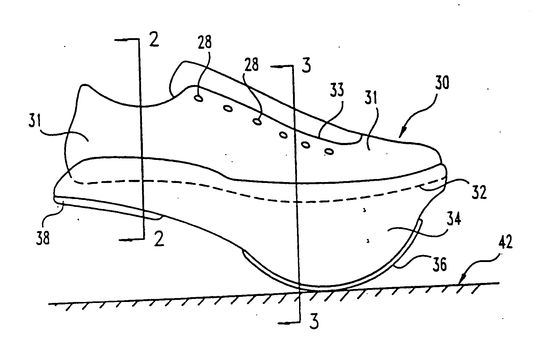
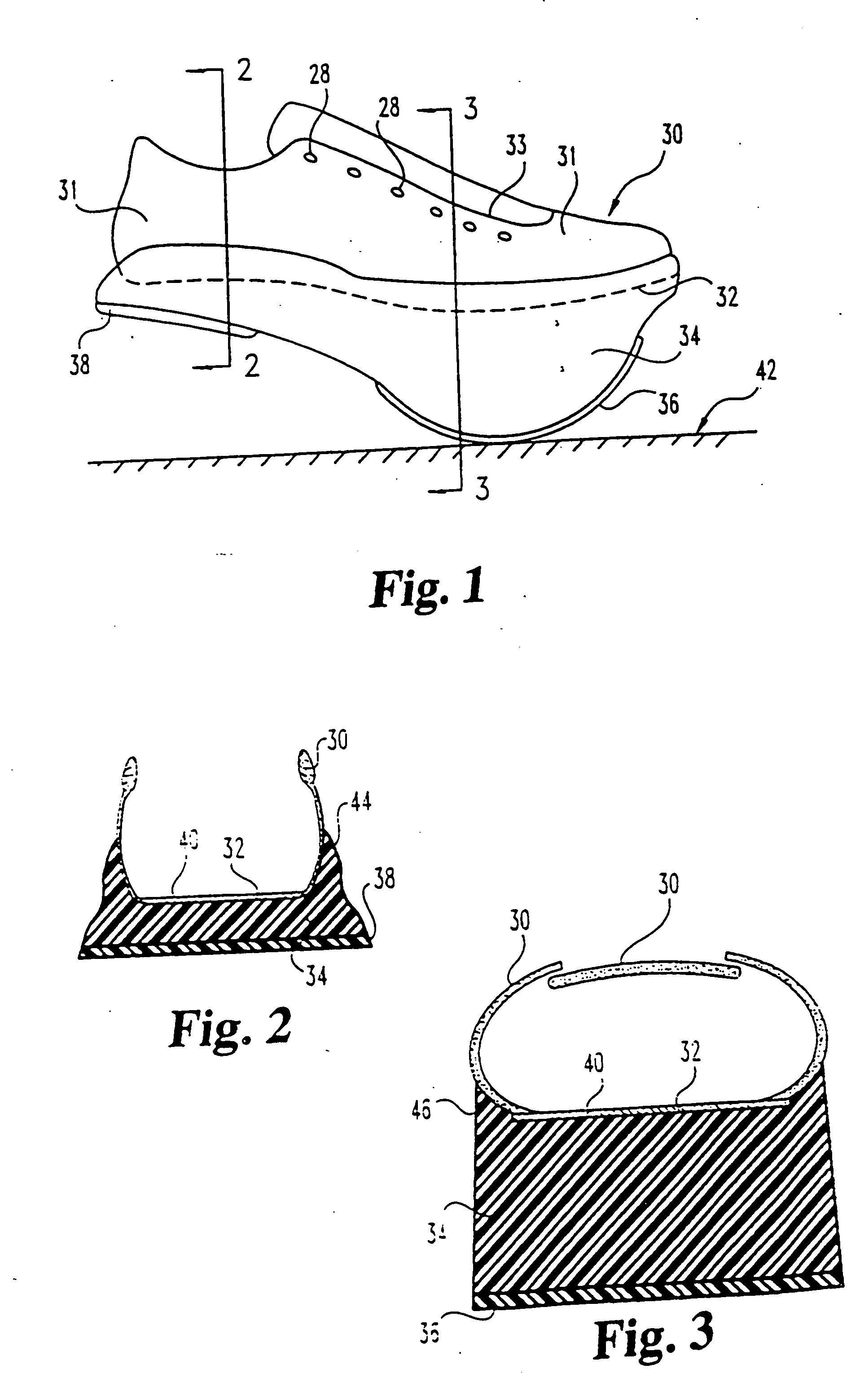
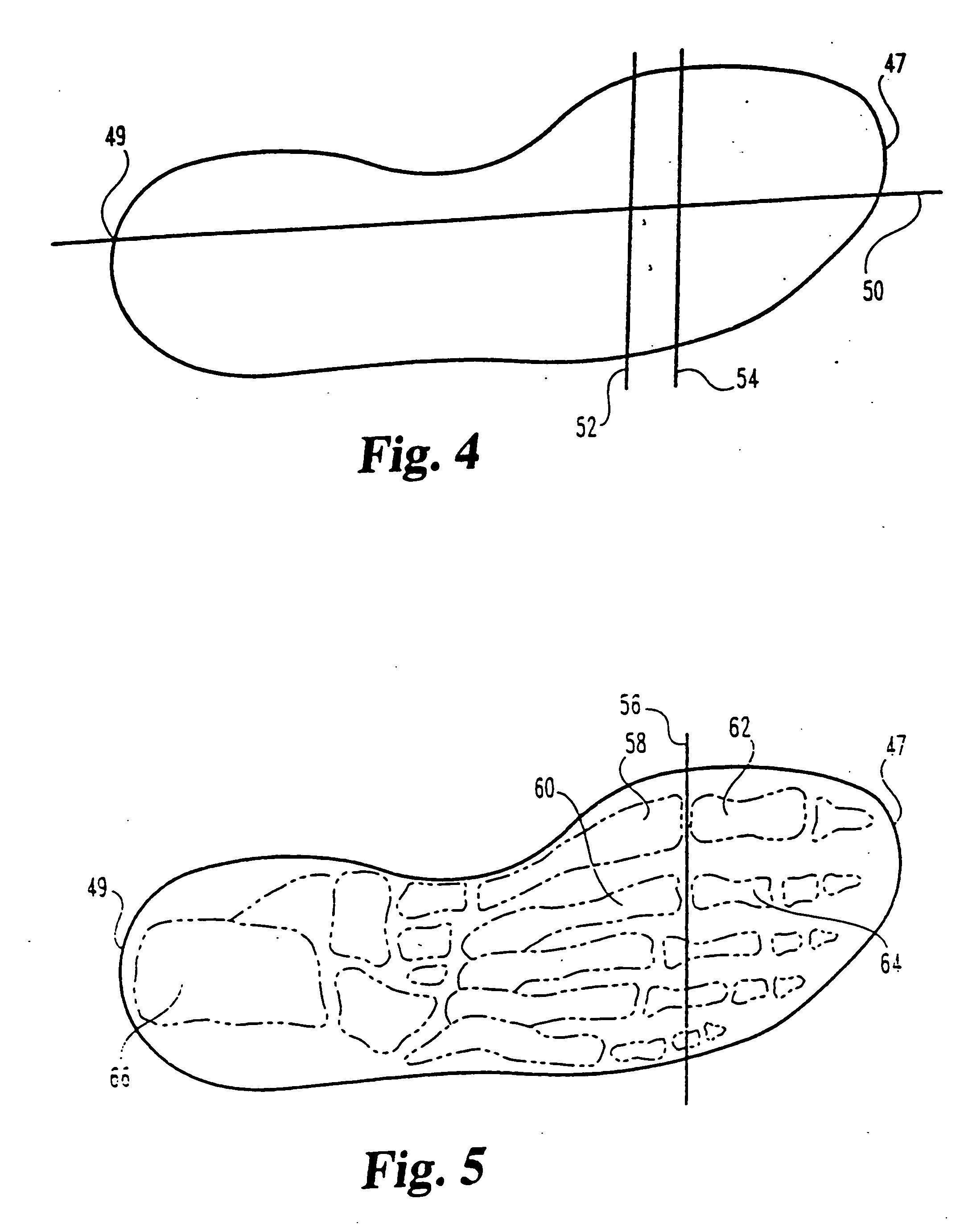
[0055] Referring to FIG. 1, an upper 30 may be of any form desired. The upper 30 is any mechanism suitable for holding the sole of this invention in position on the foot of a wearer during use. A specific example for this preferred embodiment includes a leather vamp and quarter 31 with a U-throat opening 33. Lace holes 28 are provided for drawing the upper 30 closed about the foot with a lace (not shown). The upper 30 is secured to the top surface of the sole 32 by cement and by the inclusion of a lasting board 40 (see FIG. 2) in a California slip last construction. Any other methods and constructions may be used for the forming of an upper and its attachment to the sole of this invention. For example, string lasting, flat cement lasting, moccasin construction or welting may be employed. The upper 30 may be directly injection molded with a sole, a series of foot encompassing straps may be attached to the sole, the sole may be attached by stitching, stapling, nailing or solvent bondi...


PUM


Abstract

An improved exercise device including a sole with an upper surface on which a wearer's foot rests and a lower partially ground contacting surface. The sole has a heel, a midfoot, a forefoot and a toe region such that when the heel region lower surface and the forefoot region lower surface are in ground contact, the upper surface does not incline upwards from the forefoot to the heel region. The forefoot lower surface of the sole is generally radiused in a cylindrical curve about the line connecting the mid points of the first and second metatarsal-phalangeal joints of the wearer. When the wearer contracts their calf muscles, the heel section is lifted away from the ground, requiring work against gravity.

Description


Claims


Application Information

Patent Timeline
Owner WHATLEY IAN H
Learn More