
System and method for heuristically optimizing a large set of automated test sets

a technology of automated test sets and optimization methods, applied in adaptive control, instruments, nuclear elements, etc., can solve the problems of unfeasible execution of a complete sequence of tests, large amount of test data analyzed and interpreted, and large amount of test sequence executions, so as to reduce the amount of time that each user has to wai

Inactive Publication Date: 2005-07-14
IBM CORP
View PDF17 Cites 13 Cited by
  • Summary
  • Abstract
  • Description
  • Claims
  • Application Information

AI Technical Summary

Benefits of technology

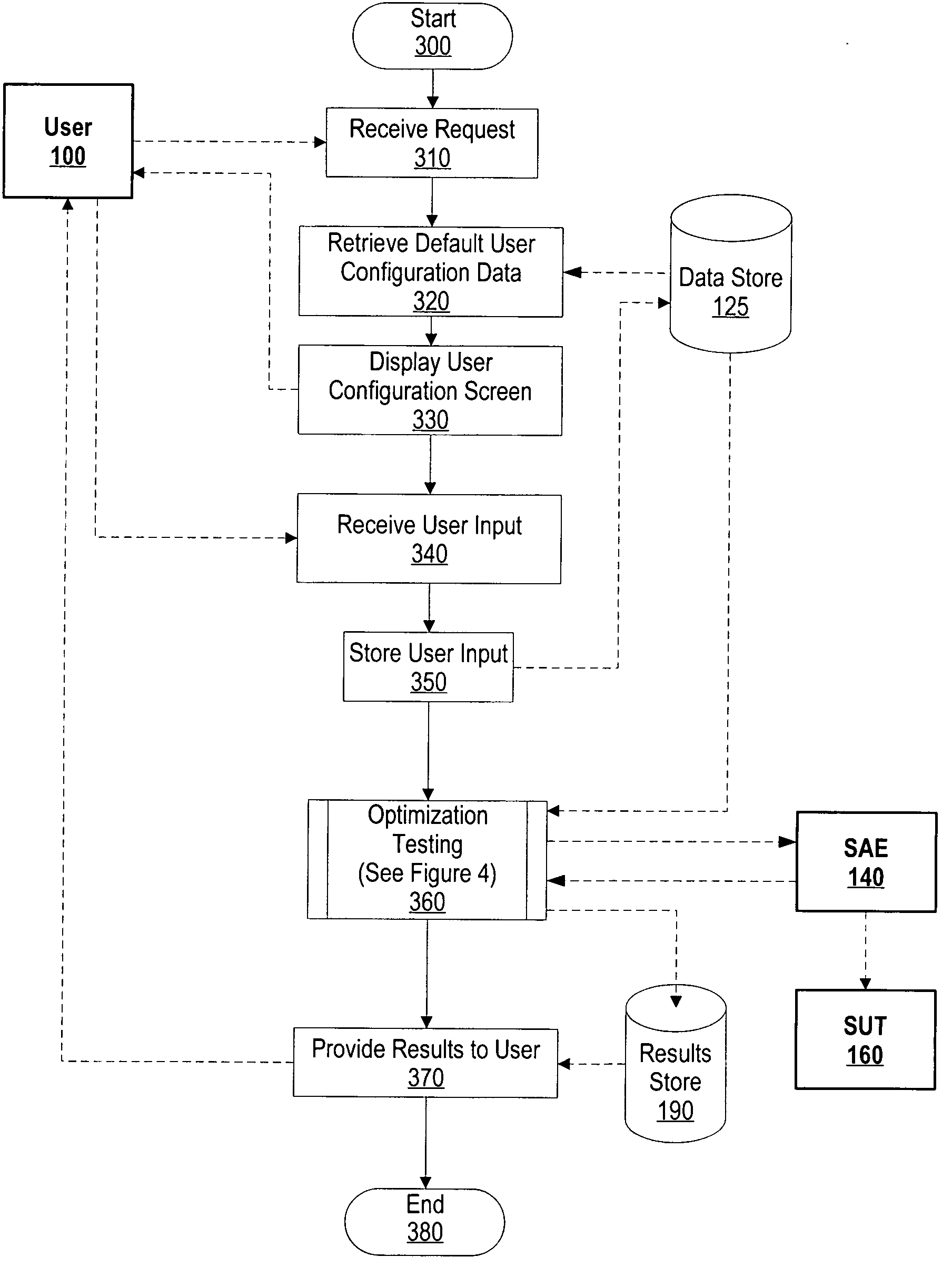
The patent describes a system that uses an automation control engine to adjust input parameters of a system automation engine based on output variable results. This helps optimize the system for a specific application. The user sends a request to the automation control engine, which retrieves baseline input parameters and sends them to the system automation engine. The system automation engine uses these parameters to test the system and receive output variables. The automation control engine then adjusts input parameters based on these output variables until the system reaches its optimal performance. The optimized input parameters are then sent to the user for configuration of the system. The technical effect of this invention is to automate the process of optimizing a system for a specific application, reducing human error and improving efficiency.

Problems solved by technology

Given the complexity of many computer systems, a challenge found is that a numerous amount of test sequence executions are required in order to adequately characterize a system under test.
In addition, another challenge found is in analyzing and interpreting the vast amount of resulting test data.
Quite frequently, it becomes unfeasible to execute a complete sequence of tests.
However, a challenge found is that this approach may not capture a computer system's optimum performance.

Method used


Image

  • System and method for heuristically optimizing a large set of automated test sets
  • System and method for heuristically optimizing a large set of automated test sets
  • System and method for heuristically optimizing a large set of automated test sets

Examples


Embodiment Construction

[0021] The following is intended to provide a detailed description of an example of the invention and should not be taken to be limiting of the invention itself. Rather, any number of variations may fall within the scope of the invention which is defined in the claims following the description.

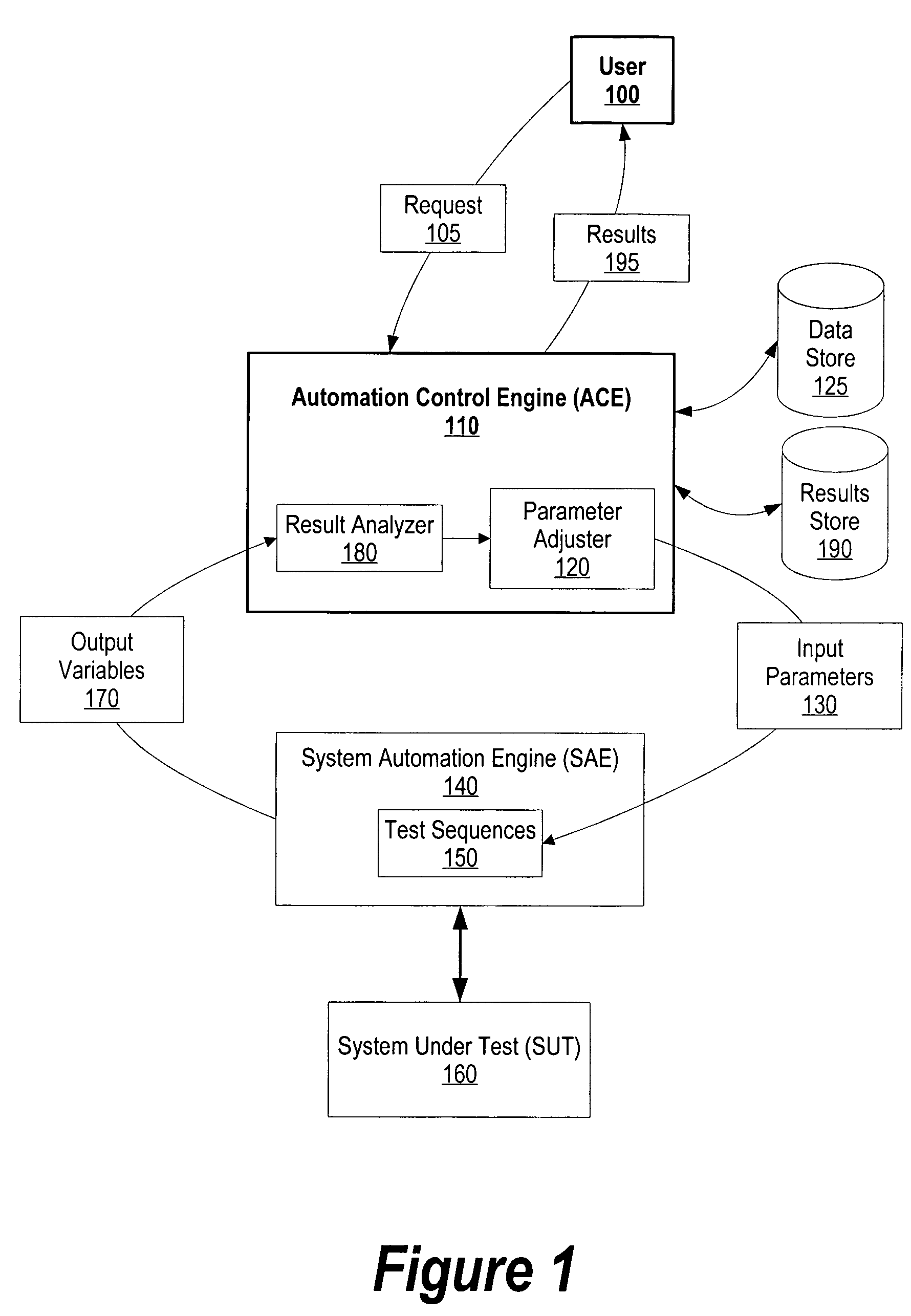
[0022]FIG. 1 is a diagram showing an automation control engine optimizing input parameters for a system automation engine in order to meet particular performance goals. User 100 wishes to optimize his system while executing system under test (SUT) 160. For example, user 100 may be managing a web service whereby the user wishes to configure his system such that the web service can receive a maximum amount of users and, at the same time, minimize the amount of time that each user has to wait for a response.

[0023] User 100 sends request 105 to automation control engine (ACE) 110. Automation control engine 110 acts as a front end to system automation engine 140 and is responsible for adjusting i...


PUM


Abstract

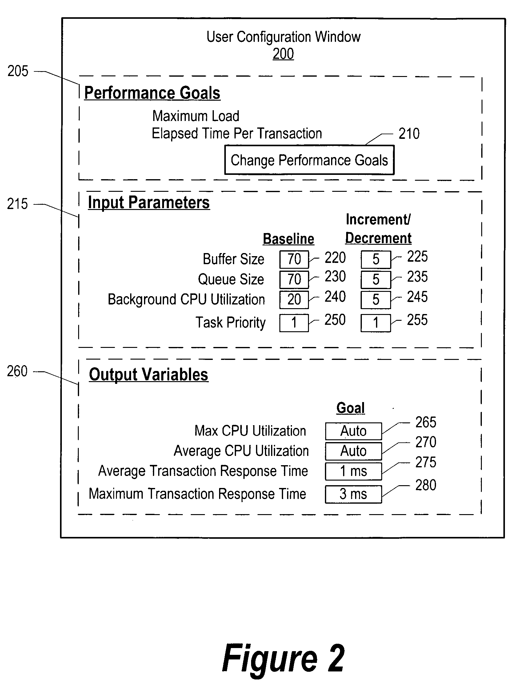
A system and method for heuristically optimizing a large set of automated test sets is presented. An automation control engine is used as a front end to a system automation engine. The automation control engine provides a set of input parameters, such as a buffer size and queue size, to the system automation engine. The system automation engine uses the input parameters along with a set of test sequences, to test a system under test. The system automation engine receives output variables from the system under test based upon the test, and sends the output variables to automation control engine. The automation control engine adjusts the input parameter values until the output variables meet one or more performance goals.

Description

BACKGROUND OF THE INVENTION [0001] 1. Technical Field [0002] The present invention relates in general to a system and method for heuristically optimizing a large set of automated test sets. More particularly, the present invention relates to a system and method for heuristically adjusting input parameters based upon output variables in order to meet one or more performance goals. [0003] 2. Description of the Related Art [0004] An automated test system usually includes two primary components which are a system under test and a system automation engine. A set of input parameters and scripts drives the system automation engine which, in turn, drives the system under test. A typical system automation engine establishes environmental conditions, such as particular load environments, and tests the system under test using a set of input parameters. While testing, the system automation engine collects a set of data (i.e. output variables) from the system under test. After testing, the syste...

Claims


Application Information

Patent Timeline
Patent Type & Authority Applications(United States)
IPC IPC(8): G05B13/02G06F11/30
CPCG06F11/3684
Inventor JAGER, HAYORIVERA, THEODORE F.TATE, ADAMWILL, SCOTT A.
Owner IBM CORP
Learn More