
Inspection device of winding appearance of tape and improvement processing method for the same

a technology of inspection device and winding appearance, which is applied in the direction of speed-changing/reversing arrangement, applications, instruments, etc., can solve the problems of inability to inspect the damage to the projecting part of the tape from the winding surface formed by the tape edges, and inability to obtain good winding appearance of magnetic tape. , to achieve the effect of good winding appearan

Inactive Publication Date: 2005-07-07
FUJIFILM CORP
View PDF13 Cites 1 Cited by
  • Summary
  • Abstract
  • Description
  • Claims
  • Application Information

AI Technical Summary

Benefits of technology

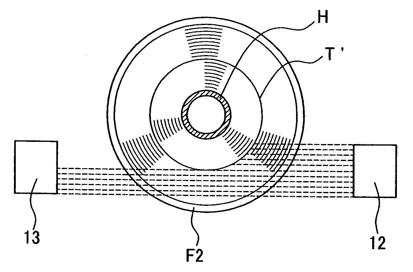
[0014] According to one exemplified aspect of the present invention, there is provided a winding appearance inspection device of the tape, for example. When the winding appearance of the tape wound on the roll body core having an opaque flange is inspected, by irradiating the light from the light projector along the winding surface of the tape, the light arrives at the receiver passing through between the winding surface and the flanges. Here, the light partially passes near the roll body core, and when the tape projects from the winding surface, the light is certainly interrupted by this projected tape, and the quantity of the light received by the receiver decreases compared with a regular state without the projected tape. Accordingly, even if the tape is wound on the roll body core having an opaque flange formed, the winding appearance can be inspected certainly.
[0019] In order to overcome the second problem, in the winding appearance improvement processing method of the magnetic tape, after predetermined quantity of the magnetic tape is taken up on the roll body core of the tape reel, predetermined time heat treatment of the magnetic tape is applied at a temperature just below a glass transition temperature of the material used for a support base of the magnetic tape, so that a natural curl may be effectively formed.
[0020] According to another exemplified aspect of the present invention, there is provided a winding appearance improvement processing method of the magnetic tape. Wherein after predetermined quantity of the magnetic tape is taken up on the roll body core of the tape reel, predetermined time heat treatment of the magnetic tape is applied at a temperature just below a glass transition temperature of the material used for a support base of the magnetic tape, so that a natural curl may be effectively formed in the winding appearance of the magnetic tape taken up on the tape reel. Thus, the winding appearance of the magnetic tape can always be maintained in a good winding appearance. Consequently, the disturbed winding appearance of the magnetic tape taken up on the tape reel is avoided, when using the magnetic tape cartridge constituted including the tape reel.
[0022] In addition, according to the exemplified aspect of the present invention, there is provided a winding appearance improvement processing method of the magnetic tape. Wherein predetermined time heat treatment of the magnetic tape is applied at a temperature lower than a glass transition temperature of the material used for the support base of the magnetic tape by 5 to 10° C., so that a natural curl may be effectively formed. Especially when polyethylene terephthalate (PET) and polyethylene naphthalate (PEN) are used for the support base of the magnetic tape, by applying the heat-treatment onto the magnetic tape at a temperature just below a glass transition temperature, the natural curl may be more effectively obtained.

Problems solved by technology

As for the tape thus taken up on the tape reel, when a winding appearance is not in good state, the magnetic tape of good appearance is not obtained, and also the projecting part of the tape from a winding surface formed by tape edges may be damaged when dropped.
However, in an inspection device that inspects a winding appearance disclosed in JP-A-2000-337827, the inspection of the winding appearance is enabled when the flange formed in the roll body core is transparent, whereas, when the flange is opaque, it is impossible to inspect the winding appearance of the magnetic tape.
Therefore, when the flange is provided in the roll body core, the winding appearance of the magnetic tape cannot be inspected.
Moreover, in this device, it takes time for the measuring device to be approached to the magnetic tape or spaced apart therefrom, or it takes time for the pressure to be stabilized after suction of the air is performed.
Moreover, when the tape is taken up on the tape reel already incorporated in the cassette, in order to improve disturbed winding, a method for mitigating the disturbed winding by using an endless belt and a touch roll cannot be used.
In addition, even if the winding appearance of the tape is improved by using the endless belt or the touch roll, the disturbance may be generated while repeatedly using the tape.
That is, there is involved a problem such that the winding appearance of the magnetic tape MT can not be maintained in a fixed winding appearance.

Method used


Image

  • Inspection device of winding appearance of tape and improvement processing method for the same
  • Inspection device of winding appearance of tape and improvement processing method for the same
  • Inspection device of winding appearance of tape and improvement processing method for the same

Examples


first embodiment

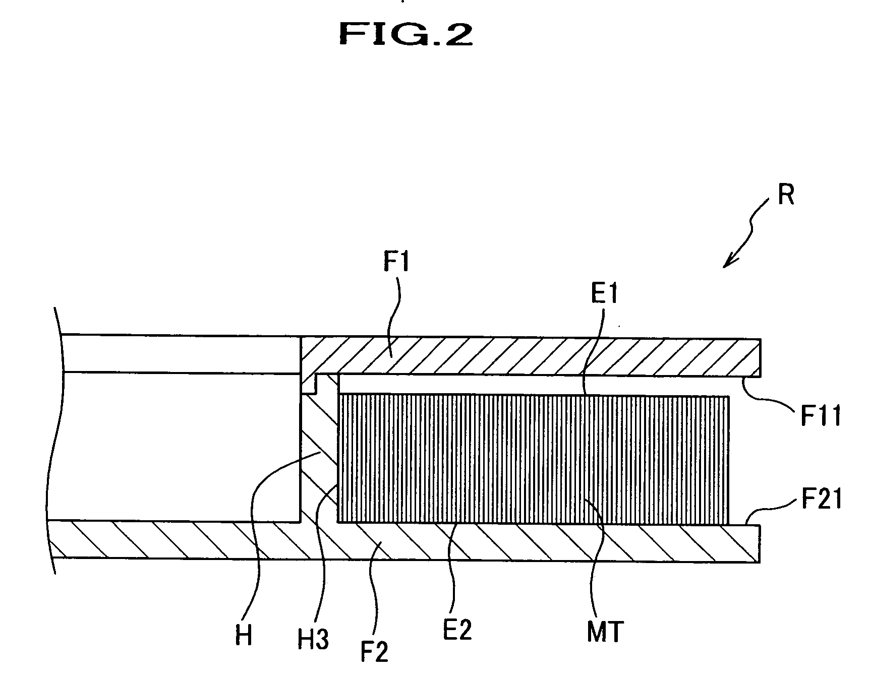
[0047] By applying the present invention, this embodiment shows a winding appearance inspection device of film T (tape) wound on roll body core H (roll body core) of tape reel R. Wherein upper flange F1 and lower flange F2 are formed on both ends of the roll body core (roll body core) H.

[0048] As shown in FIG. 4, winding appearance inspection device 10 of this invention mainly includes a main body 11, a light transmissive device 12, and a receiver 13. The main body 11 mainly includes a base part 11a formed in a nearly rectangular form in plan view, a reel installation part 11b for installing the tape reel R, a light transmissive device installation part 11c for installing the light transmissive device 12, and a light receiver installation part 11d for installing the light receiver 13.

[0049] The reel installation part 11b is formed so that it may project from nearly the center of the base part 11a. The face gear, which is not shown, for receiving rotation driving force is formed on...

second embodiment

[0058] This embodiment presents an inspection device that inspects a winding appearance of magnetic tape cartridge C having two tape reels R of the first embodiment. The components and portions of the same designation as those in the drawings used for the explanation for the first embodiment are designated the same numerals and signs, omitting and simplifying the overlapping explanation.

[0059] As shown in FIG. 7, a winding appearance inspection device 20 mainly includes a light projector 21 that irradiates light along the winding surface S of the magnetic tape (tape) toward roll body core H, and a receiver 22 that receives the light from the light projector 21 which is reflected by projecting magnetic tape MT′. The light projector 21 is installed so that the light may be irradiated from the exterior of magnetic tape cartridge C to roll body core H of inside. Therefore, the light projector 21 is installed in the position where the roll body core H of inside can be examined with open...

third embodiment

[0067] This embodiment, as shown in FIG. 10, presents an inspection device of the winding appearance of the magnetic tape cartridge C of the second embodiment. Therefore, the components and portions of the same designation as those in the drawings used for the explanation for the second embodiment are designated the same numerals and signs, omitting and simplifying the overlapping explanation.

[0068] As shown in FIG. 10, an winding appearance inspection device 30 mainly includes a lighting device 31 (light projector) that irradiates the light heading for the roll body core H along the winding surface S of the magnetic tape MT, and a CCD camera (imaging device) 32 that images the light from the lighting device 31 reflected by the magnetic tape MT′ that projects from the roll body core H and the winding surface S. Lighting device 31 is a small device using an optical fiber. Therefore, if only a luminescence portion is pulled out by a suitable method and fixed, the installation to a na...


PUM

PropertyMeasurementUnit
glass transition temperatureaaaaaaaaaa
speedaaaaaaaaaa
speedaaaaaaaaaa

Abstract

To provide a winding appearance inspection device of a tape capable of gathering a line speed in an inspection process, as well as capable of inspecting a winding appearance of the tape wound on a roll body core, even in a reel having a flange formed in a roll body core (a roll body core). Winding appearance inspection device 10 serves as a device that evaluates the winding appearance of the tape such as film T or the like wound on roll body core H, comprising light projector 12 that irradiates a light along winding surface S of the tape such as film T or the like that at least partially passes near the roll body core H, and receiver 13 that receives the light.

Description

DETAILED DESCRIPTION OF THE INVENTION TECHNICAL FIELD OF THE INVENTION [0001] This invention relates to an inspection device of a tape that inspects a winding appearance such as a magnetic tape or web wound on a roll body core, and an improvement processing method capable of improving a disturbed winding of the tape taken up on a tape reel. BACKGROUND OF THE INVENTION [0002] Generally, a tape in a belt-like form of paper, plastic film, or metal foil, is shipped in a state of taken up on a tape reel. As for the tape thus taken up on the tape reel, when a winding appearance is not in good state, the magnetic tape of good appearance is not obtained, and also the projecting part of the tape from a winding surface formed by tape edges may be damaged when dropped. Therefore, inspection about the winding appearance has been performed conventionally. [0003] The conventional inspection device of the winding appearance is disclosed in JP-A-2000-337827. In the inspection device, the winding ap...

Claims


Application Information

Patent Timeline
Patent Type & Authority Applications(United States)
IPC IPC(8): B29C71/02G11B15/02G11B15/16G11B15/44G11B15/52G11B15/66G11B23/087
CPCB29C71/02B29K2067/00B29L2017/008G11B15/02G11B23/0875G11B15/44G11B15/52G11B15/66G11B15/16
Inventor HAYASHI, YOICHITADA, NOBUYUKI
Owner FUJIFILM CORP
Learn More