
Rheological and calorimetric testing method

a rheological and calorimetric testing and measuring device technology, applied in the direction of rotary stirring mixers, instruments, transportation and packaging, etc., can solve the problems of large errors in measured values, inaccuracy of rheometers, and significant inaccuracy in calculating the shear force applied to sample fluid, so as to minimize inaccuracy, accurately evaluate, and minimize inaccuracy

Inactive Publication Date: 2005-06-30
GCP APPL TECH INC
View PDF9 Cites 33 Cited by
  • Summary
  • Abstract
  • Description
  • Claims
  • Application Information

AI Technical Summary

Benefits of technology

The device provides accurate rheological measurements by maintaining fluid homogeneity and minimizing particle segregation, enabling precise evaluation of rheological properties over time without transferring samples, suitable for high-throughput testing of hydratable cementitious mixes.

Problems solved by technology

Meeten observed that rheometers may be inaccurate due to so-called end effects, such as “slippage at the wall” of particle-containing liquid in the container cup, and such as “particle migration” towards the bottom of the cup due to gravity.
Such effects can lead to significant inaccuracies in calculating shear forces applied to the sample fluid, and, hence, its rheological properties.
This can, in turn, reduce significantly the measured viscosity and yield stress, consequently leading to large errors in measured values.
The effect of gravity is to reduce the particle content in the sample zone where the yield stress is measured, and therefore the inaccuracy for rheological measurement is increased for samples mixed using high shear forces.
Furthermore, the build-up of solids below the rotor / stator device may cause extra torque to be transmitted to the stator, further increasing error.
This centrifugation effect decreased the number of particles near the inside of the rotor, thus increasing the inaccuracy of the torque measurement and data obtained.
The present inventors believe that the use of a recirculating pump, as taught by Meeten, could introduce problems for evaluating relatively stiff and viscous mixes such as concrete and mortar.
This is because such cementitious mixes, which begin to harden upon hydration, can potentially foul his hoses and pump equipment.
Moreover, it is possible that the effect of high viscous fluids in the hoses, such as cement slurries, pastes, or mortars, might tend to hinder the use of pulsing for dispersing the particles.

Method used


Image

  • Rheological and calorimetric testing method
  • Rheological and calorimetric testing method
  • Rheological and calorimetric testing method

Examples


Embodiment Construction

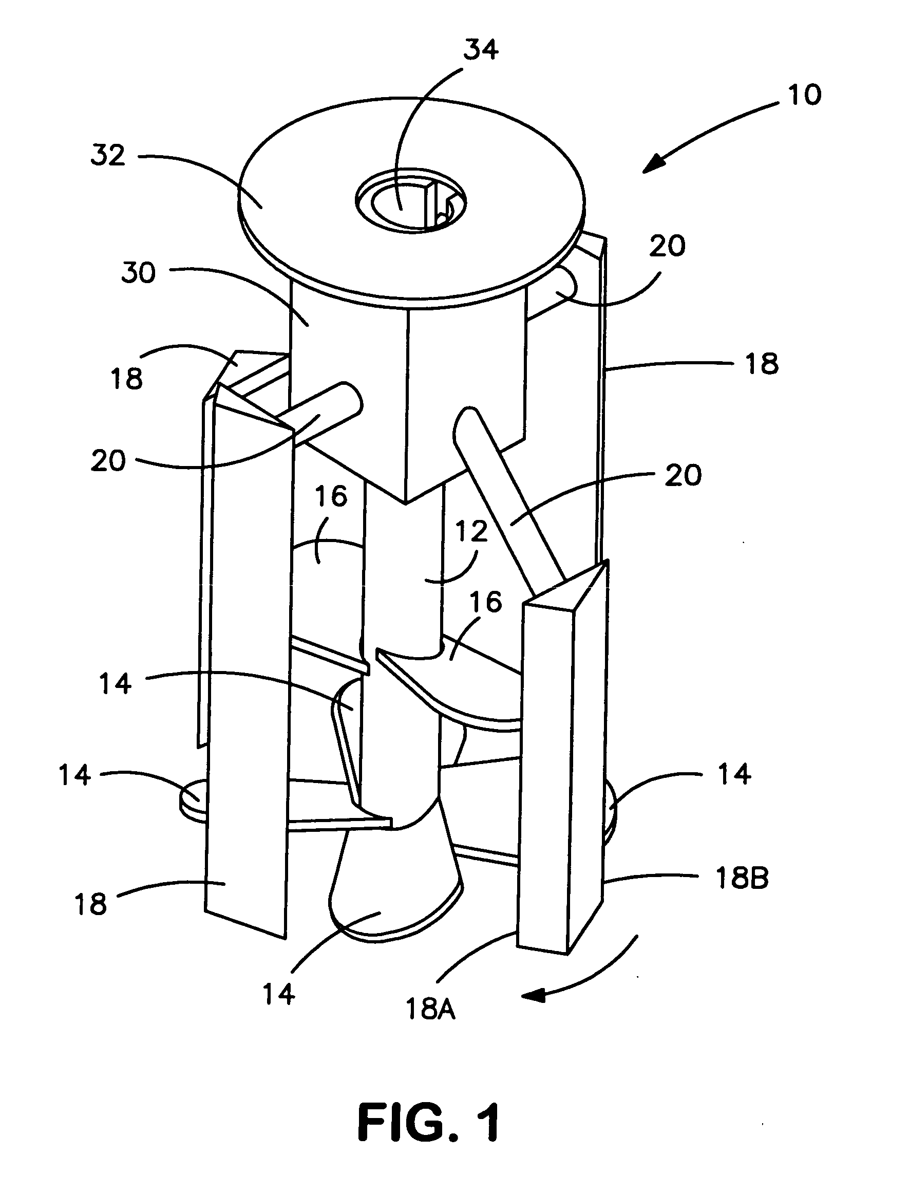
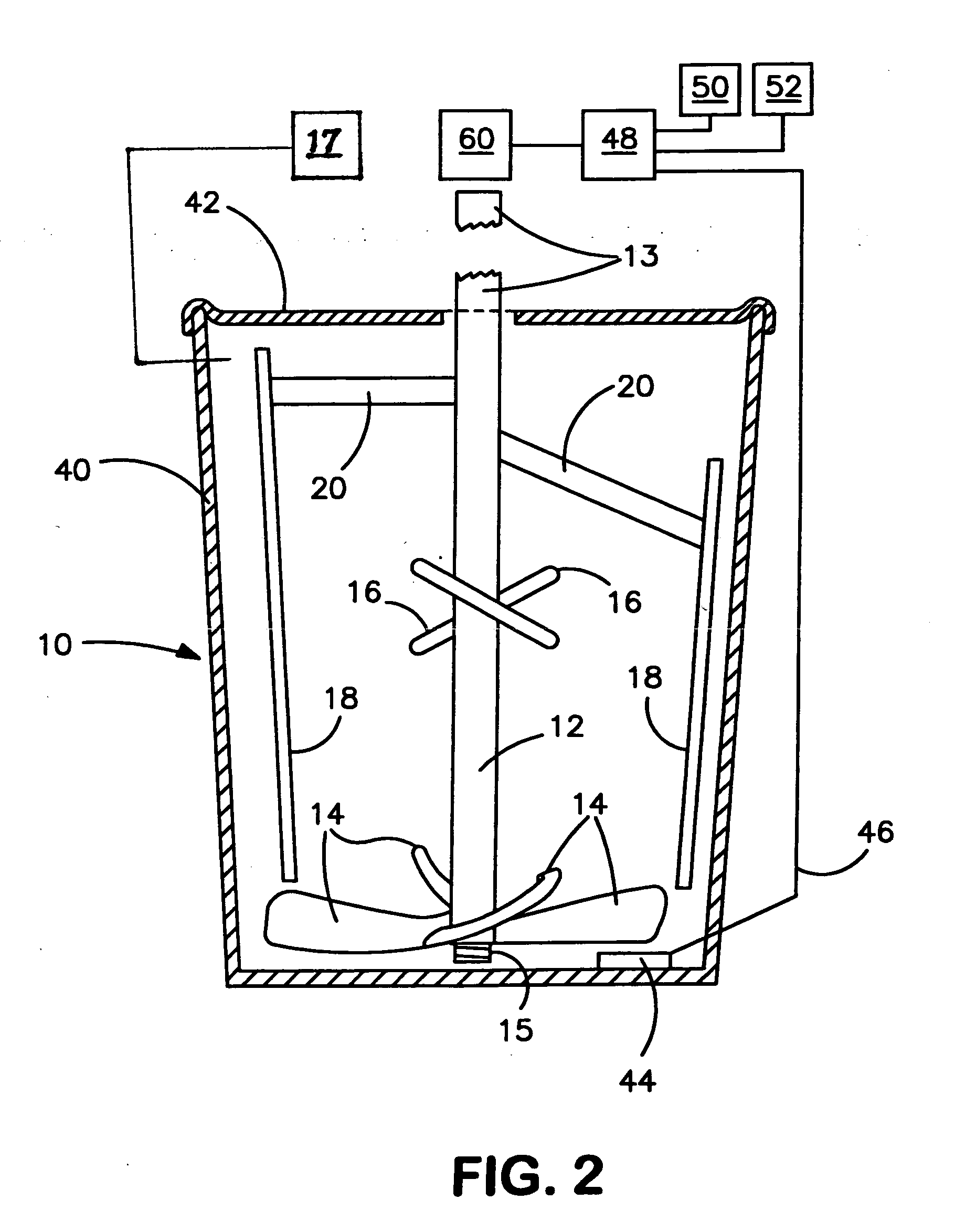
[0028] The exemplary rheomixer of the present invention is designed to work with servo-controlled electric motors (otherwise referred to as “servo-engines”) that are designed to rotate and to provide an electrical output signal that accurately corresponds to the amount of torque applied, such that, in combination with the inventive rheomixers of the present invention, fluid samples can be quickly mixed and their torque resistance on the rotated rheomixer device can be quickly and accurately measured. Such servo-engines are able to stop and start with high precision, due to the fact that their electric motors contain numerous electric coils that provide nearly-instantaneous torque. A servo-engine believed to be suitable for purposes of the present invention is available from Samey of Iceland under the tradename Control Technologies™, and other suitable servo-engines are elsewhere available.

[0029] Preferred methods of the invention for mixing involve the ability of servo-engines to a...


PUM

PropertyMeasurementUnit
rheologyaaaaaaaaaa
temperatureaaaaaaaaaa
heat measurementsaaaaaaaaaa

Abstract

Device and methods for rotationally mixing and rheological testing of sample liquids, such as cement particle suspensions, employ mixing blades and shear-resistant members having substantially noncoincident orbital paths. Rheology is assessed by measuring the resistance of the liquid to rotation of the device. Both rheological and calorimetric testing can be performed during mixing, which ensures uniformity of rheology and hence the accuracy of results.

Description

FIELD OF THE INVENTION [0001] The present invention relates to a rotational mixing and rheology measuring device suitable for use with viscous fluids, and especially for particle suspensions such as cement, mortar, and concrete slurries. BACKGROUND OF THE INVENTION [0002] As mentioned in U.S. Pat. No. 5,546,791 of Meeten, the rheology or thixotropy of granular fluid slurries, such as cement slurries or drilling mud, can be useful for determining the behaviour of the resultant material. The current standard rheology measurement, as specified by the American Petroleum Industry (API), involves testing of samples in a cup container, and placing a rotor / stator device into the cup. The rotor / stator device comprises a cylindrical, motor-driven rotor having a vaned stator coaxially mounted on the rotation axis. Rotation of the rotor applies torque to the stator. Rate of rotation is compared to the applied torque to determine rheological characteristics of the cup-contained sample. [0003] Me...

Claims


Application Information

Patent Timeline
Patent Type & Authority Applications(United States)
IPC IPC(8): B01F27/71G01N11/00G01N11/10G01N11/14G01N25/00G01N33/38
CPCB01F7/00641B01F7/063B01F15/00201B01F15/00246G01N2011/0046B01F2215/0047G01N11/14G01N33/383B01F15/00376B01F27/192B01F27/711B01F35/212B01F35/2136B01F35/22142B01F2101/28
Inventor WALLEVIK, OLAFUR H.SANDBERG, PAULMYERS, DAVID F.
Owner GCP APPL TECH INC
Learn More