
Control system for a tiled large-screen emissive display

a control system and emissive display technology, applied in static indicating devices, digital output to display devices, instruments, etc., can solve the problems of large-scale use of light-emitting arrays or displays, lcds failing to meet the high resolution and speed requirements of lcds failing to provide the bright, high light output, and large viewing angles that the large-screen display market demands. achieve the effect of reducing software complexity

Inactive Publication Date: 2005-06-23
BARCO NV
View PDF9 Cites 206 Cited by
  • Summary
  • Abstract
  • Description
  • Claims
  • Application Information

AI Technical Summary

Benefits of technology

[0007] It is therefore an object of the invention to provide a system and method for controlling and calibrating a tiled large-screen emissive display with reduced software complexity as compared with conventional systems.

Problems solved by technology

To date, the use of light-emitting arrays or displays has been largely limited to small-screen applications such as those mentioned above.
For example, LCDs fail to provide the bright, high light output, larger viewing angles, and high resolution and speed requirements that the large-screen display market demands.
However, the use of OLED technology in large-screen display applications, such as outdoor or indoor stadium displays, large marketing advertisement displays, and mass-public informational displays, is only beginning to emerge.
However, in order to handle the control algorithms for large-screen emissive displays, very complex control software with high bandwidth and a high level of processing power is required.
Although the display calibration and control method described in U.S. Pat. No. 5,739,809 provides a suitable means for controlling a display apparatus, the software control system described is very complex for use in a large-screen emissive display application.

Method used


Image

  • Control system for a tiled large-screen emissive display
  • Control system for a tiled large-screen emissive display
  • Control system for a tiled large-screen emissive display

Examples


Embodiment Construction

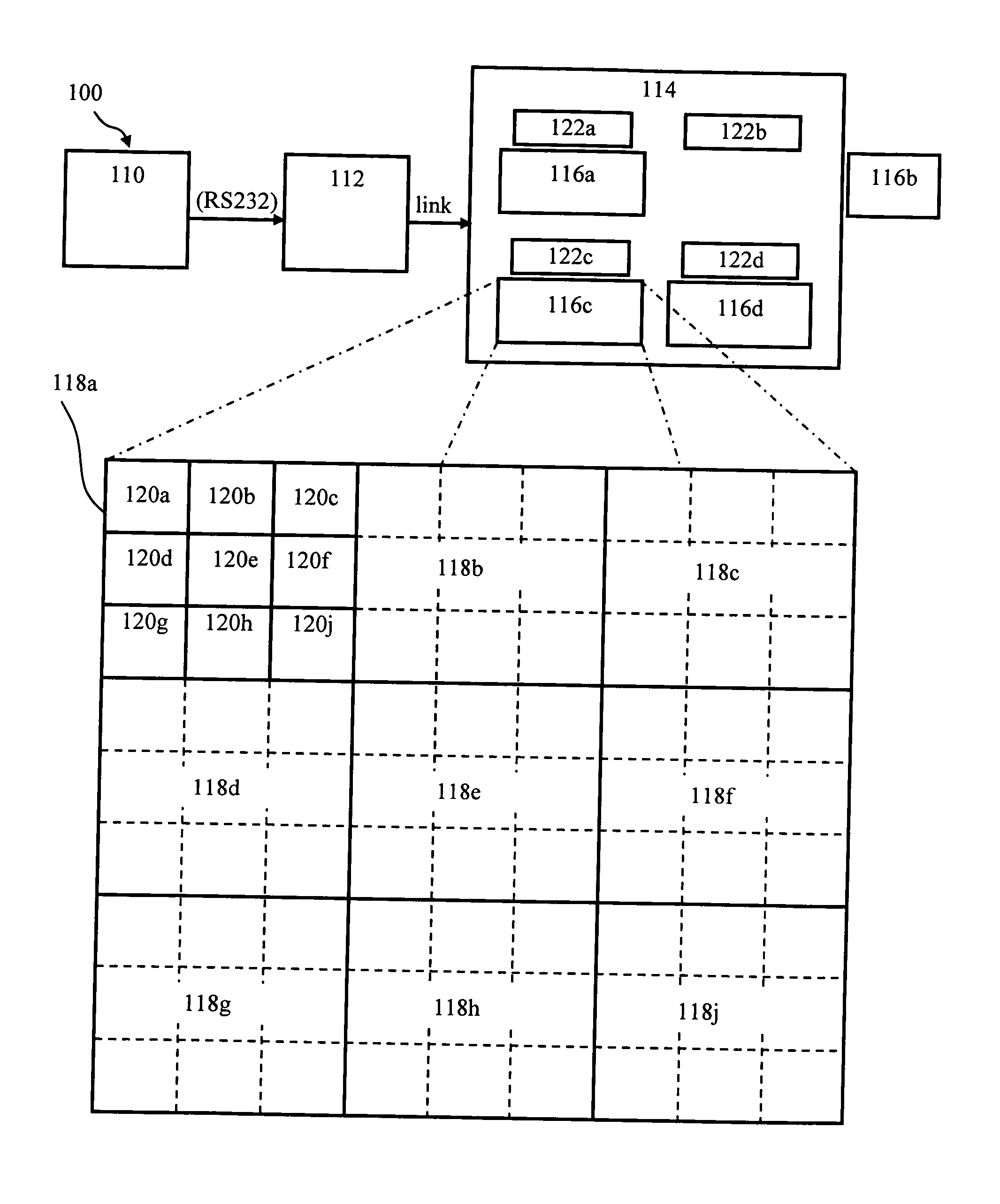
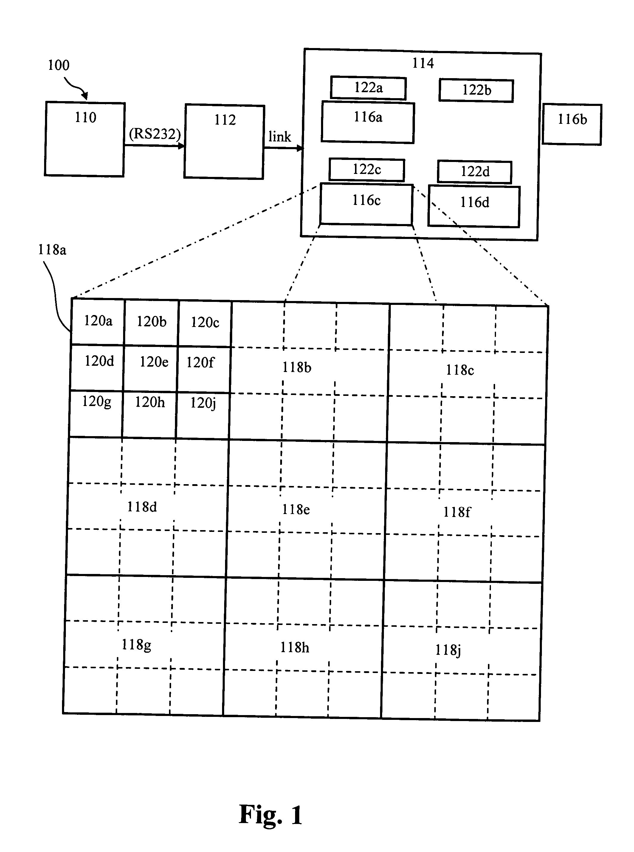
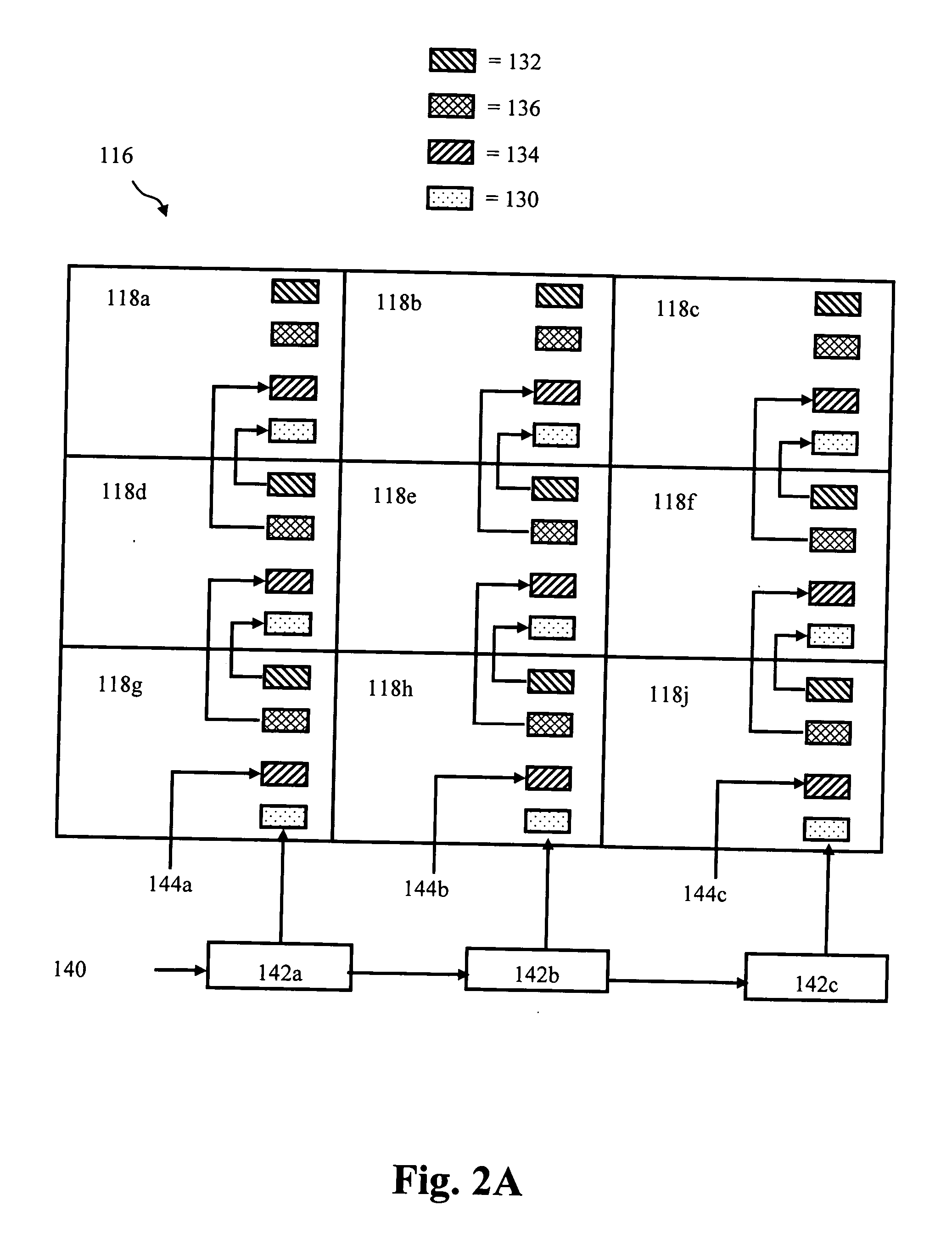
[0049] The present invention will be described with respect to particular embodiments and with reference to the drawings, but the invention is not limited thereto but only by the claims. The drawings are only schematic and are non-limiting. In the drawings, the size of some of the elements may be exaggerated and not drawn on scale for illustrative purposes.

[0050] The present invention relates to a control system for use with a modular, tiled, large-screen emissive display application. The control system of the present invention performs operations to initialize and configure an emissive display system during the physical assembly of emissive tiles, addresses the emissive display tiles, and controls the emissive display tiles for uniform image and proper image size. Furthermore, the control system of the present invention handles additional features, such as hot swap capability to replace failed emissive display tiles and a mechanism to detect a new emissive display tile, and video ...


PUM


Abstract

The present invention relates to a method of controlling a modular, tiled, large-screen emissive display application, e.g. an OLED display application. The method of controlling e.g. includes a first control level (214) for controlling the emissive devices, a second control level (212) for controlling the emissive display modules and a third control level for controlling the emissive display tiles (210). The number of control levels can be larger or it can be restricted to two levels. The method of controlling according to the present invention allows for similar control and calibration algorithms to be run at all levels, and allows for distributed processing in order to reduce bandwidth requirements and processing complexity. Furthermore, the control method of the present invention includes a method of operating and a method of monitoring a modular, tiled, large-screen emissive display.

Description

FIELD OF THE INVENTION [0001] The present invention relates to a control system and method for a modular large-screen emissive display such as an organic light-emitting diode (OLED) display. BACKGROUND OF THE INVENTION [0002] OLED technology incorporates organic luminescent materials that, when sandwiched between electrodes and subjected to a DC electric current, produce intense light of a variety of colors. These OLED structures can be combined into the picture elements, or pixels, that comprise a display. OLEDs are also useful in a variety of applications as discrete light-emitting devices or as the active element of light-emitting arrays or displays, such as flat-panel displays in watches, telephones, laptop computers, pagers, cellular phones, calculators, and the like. To date, the use of light-emitting arrays or displays has been largely limited to small-screen applications such as those mentioned above. [0003] The market is now, however, demanding larger displays with the flex...

Claims


Application Information

Patent Timeline
IPC IPC(8): H01L51/50G06F3/14G06F3/147G09G3/20G09G3/22G09G3/30G09G3/32G09G5/00
CPCG06F3/1446G09G2360/144G09G3/3208G09G2300/026G09G2320/0233G09G2320/0276G09G2320/0295G09G2320/041G09G2320/043G09G2320/0626G09G2320/0666G09G2320/0693G09G2330/02G09G2330/10G09G3/22G09G3/30
Inventor TANGHE, GINODEDENE, NELEHILLE, HERBERT VANTHIELEMANS, ROBBIE
Owner BARCO NV
Learn More