Method and system for modelling bone structure
a technology of bone structure and modeling method, applied in the field of structural and mechanical model and modeling methods of human bone, can solve the problems of many biomechanical issues relating to bone that are still not understood, the behavior of osteon structural components cannot be explained, and the function and behavior of bone are not understood
- Summary
- Abstract
- Description
- Claims
- Application Information
AI Technical Summary
Benefits of technology
Problems solved by technology
Method used
Image
Examples
example 1
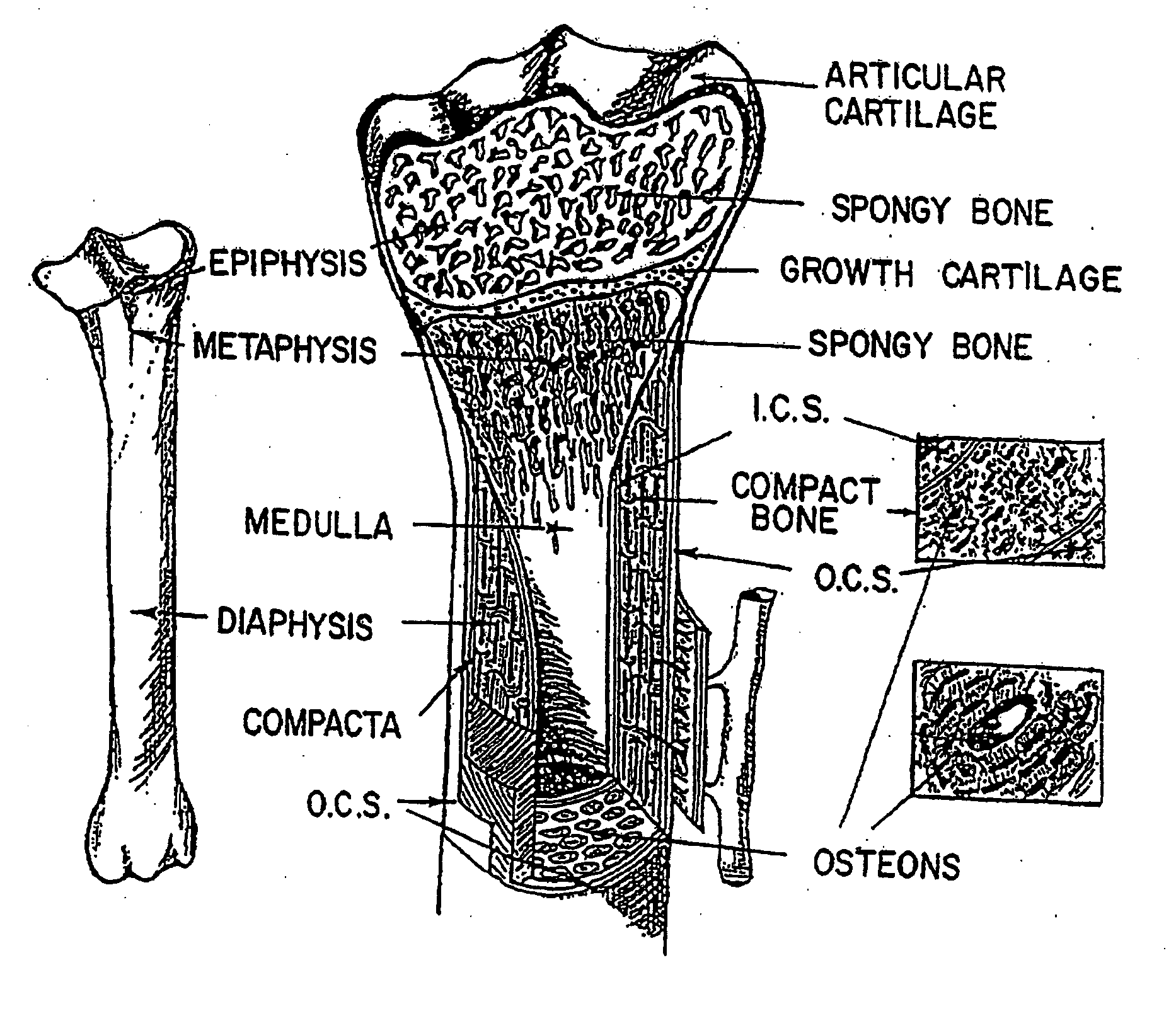
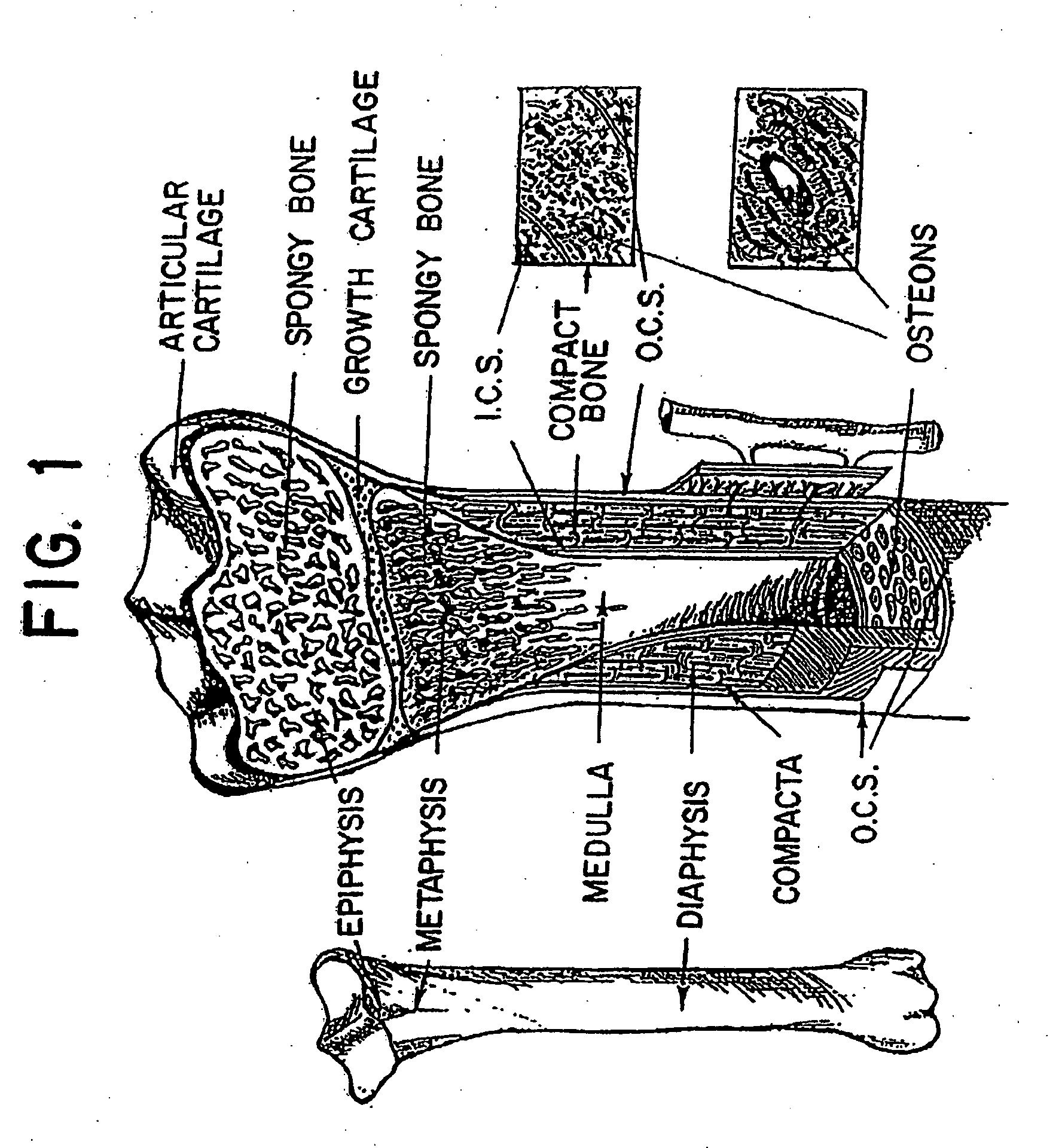
[0163] To produce a model of the present invention, compact bone is subjected to any method that may produce non-invasive slices of biological structures that are known in the art (i.e., μCT-scan or micro computerized tomography). Images then are stored in a computer and a 3-dimensional-reconstruction is applied using a standard method known in the art (see e.g. Materialise, XYZ Scientific Applications, Inc. Livermore, Calif.). The high resolution of a μCT-scan (about 30 μm) allows for determination of the outline of osteons, of osteons' vascular canals and interstitial bone. Also the 3D-reconstruction shows varying shades of gray, which represent the degree of calcification. Osteons are filled with structure by means of the two lamellar types (bright and extinct lamellae), which have been previously assembled. The criteria by which the lamellar structure is drawn into each osteon follows the distribution of alternate osteons (Hert, et al. 1994) and the distribution of dominant coll...
example 2
[0181] A. Sample Preparation, Measurements, and Experimentation
[0182] Sample preparation and selection in this example will be achieved by applying the Ascenzi A. et al. (1994) methodology. Accurate sample preparation is important, and the Ascenzi method is preferred. The femoral shafts of human corpses free from evident skeletal faults will provide the bone material for the study. Longitudinal shaft segments about 30 mm long will be first sawn off, and longitudinal sections slightly thicker than an osteon (350 μm) will then be prepared using a Leitz rotating-saw microtome. A continuous water-spout will be incorporated to prevent any overheating of the material. Osteon samples will then be isolated from the sections. The features determining sample selection will be the degree of calcification and the orientation of the collagen bundles and crystallites. Microradiographic examination, preferably according to Amprino and Engström (1952), will allow the selection of fully calcified o...
example 3
Osteon Viscous Behavior and Mucopolysaccharide Content
[0297] This Example reports two studies which provided information on osteon viscous behavior. The results show that the mucopolysaccharide content is higher in alternate rather than longitudinal osteons. These osteons can be modeled accordingly.
[0298] The bone material came from the femoral shafts of human cadavers, aged between 18 and 55, obtained in accordance with American regulation and free from evident skeletal faults and infectious diseases such as AIDS, hepatitis A and B, and syphilis.
[0299] First Study
[0300] Six osteon samples, obtained as described below, were subjected to twist and hold testing to evidence their viscous behavior through relaxation. Osteon sample isolation was achieved by applying the methodology described in Ascenzi A. et al. (1994). By means of a rotating-saw microtome, longitudinal segments about 30 mm long were first sawn from the femoral shaft. The segments were sliced in 350 μm thick longitud...
PUM
 Abstract
Description
Claims
Application Information
 - R&D
- Intellectual Property
- Life Sciences
- Materials
- Tech Scout
- Unparalleled Data Quality
- Higher Quality Content
- 60% Fewer Hallucinations
Browse by: Latest US Patents, China's latest patents, Technical Efficacy Thesaurus, Application Domain, Technology Topic, Popular Technical Reports.
© 2025 PatSnap. All rights reserved.Legal|Privacy policy|Modern Slavery Act Transparency Statement|Sitemap|About US| Contact US: help@patsnap.com


