
Atraumatic endotracheal tube introducer and atraumatic intubation methods

Inactive Publication Date: 2005-06-16
RES FOUND OF THE STATE UNIV THE
View PDF14 Cites 9 Cited by
  • Summary
  • Abstract
  • Description
  • Claims
  • Application Information

AI Technical Summary

Benefits of technology

[0011] The invention comprises a flexible endotracheal tube introducer (“introducer”) for slidably removable disposition within an endotracheal tube (“ETT”), said introducer having a wall defining a lumen extending between a proximal end and a di

Problems solved by technology

When an ETT is advanced over the fiberscope or a tube exchanger, the distal tip of the ETT may impinge on the glottis, the epiglottis, the larynx, or other anatomy of the airway, causing trauma and resisting further advancement into the trachea.

Method used


Image

  • Atraumatic endotracheal tube introducer and atraumatic intubation methods
  • Atraumatic endotracheal tube introducer and atraumatic intubation methods
  • Atraumatic endotracheal tube introducer and atraumatic intubation methods

Examples


Embodiment Construction

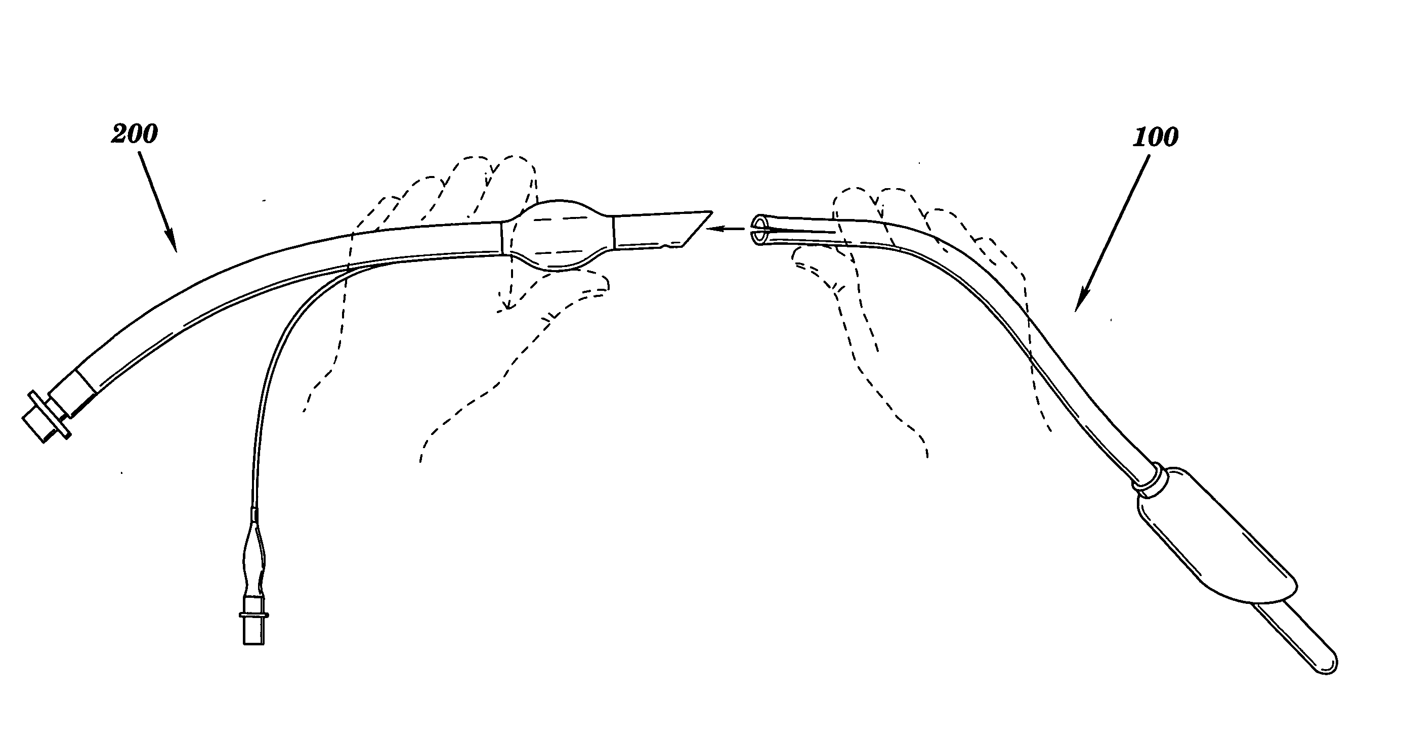
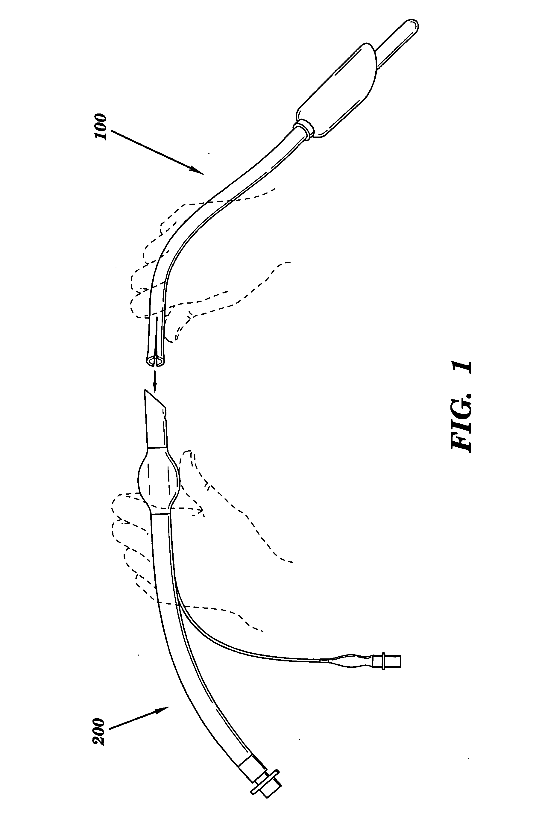
[0036] As show in FIG. 1, the present invention comprises a flexible endotracheal tube introducer (“introducer”) 100 for slidably removable disposition within an exemplary endotracheal tube (“ETT”) 200, such as, for example, a No. 6.5, No. 7.0, No. 7.5 or No. 8.0 adult ETT.

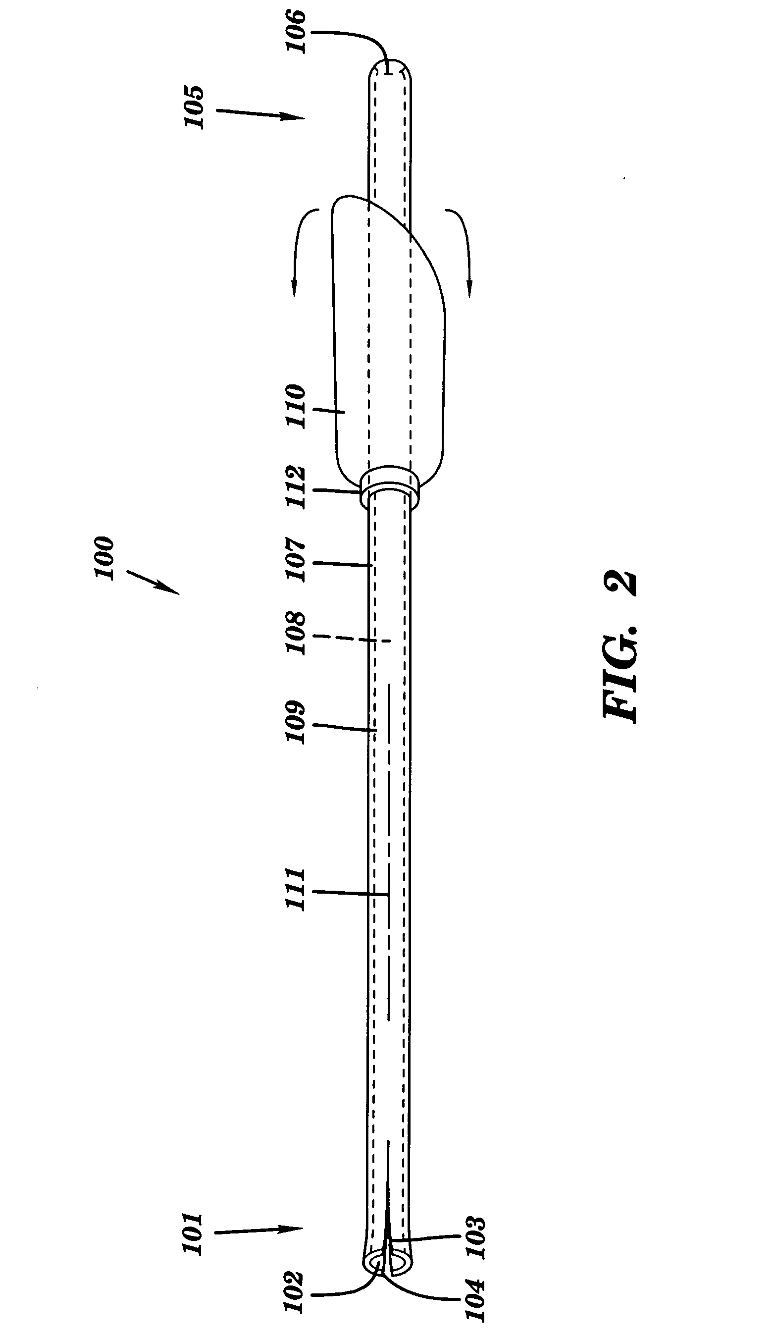
[0037] As shown in FIG. 2, introducer 100 comprises a tubular member 109 having a longitudinal axis 111, and having a lumen 108, extending between a split proximal end 101 and a distal end 105 of tubular member 109 and defined by a cylindrical wall 107 that is circumscribed by a ring 112 to which there is invertibly attached a shroud 110.

[0038] Cylindrical wall 107 of introducer 100 has an inner diameter of about 4.5 millimeters, a thickness of about 1 millimeter and an outer diameter of about 6.5 millimeters. Cylindrical wall 107 of introducer 100 has an outer diameter that is less than an inner diameter of exemplary ETT 200 (shown in FIG. 1).

[0039] A first slit 103 in split proximal end 101 of tubular member ...


PUM


Abstract

The present invention is an endotracheal tube introducer (“introducer”) that slides within an endotracheal tube. The introducer has a tubular wall that defines a lumen extending between a proximal end and a distal end of the introducer. The tubular wall has an outer diameter that is less than an inner diameter of the endotracheal tube. The tubular wall is circumscribed by an invertible shroud. The invertible shroud flexes distal-ward (“forward”) proximal-ward (“rearward”). The proximal end of the introducer is introduced into a distal end of the endotracheal tube and the shroud is manually retroflexed rearward to cover the sharp margins of the end of the endotracheal tube prior to its insertion into a patient's airway. After the endotracheal tube has been properly positioned, the introducer is withdrawn, the motion of its withdrawal anteflexing the shroud forward for removal through the endotracheal tube.

Description

BACKGROUND OF THE INVENTION [0001] 1. Technical Field [0002] The present invention pertains to the field of endotracheal intubation. [0003] 2. Related Art [0004] Endotracheal intubation is a procedure for creating an artificial airway in a patient by inserting an endotracheal tube (“ETT”) into a patient's trachea through the patient's nose or mouth. [0005] Fiberoptic endotracheal intubation is an intubation technique that utilizes a fiberoptic endoscope (“fiberscope”) to facilitate the proper placement or exchange of an ETT. A health care provider, using the direct visualization provided by the eyepiece of the fiberscope, directs the fiberscope, with an ETT pre-loaded (“piggy-backed”) on the fiberscope's insertion cord, into a patient's trachea. Using the fiberscope as a guide wire, a distal tip of the ETT is then advanced over the fiberscope into the trachea between and beyond the vocal cords. [0006] In an endotracheal tube exchange, an in-place ETT in a patient is withdrawn over a...

Claims


Application Information

Patent Timeline
IPC IPC(8): A61M16/04
CPCA61M16/0488A61M16/0484
Inventor PEKAR, ALEXANDR
Owner RES FOUND OF THE STATE UNIV THE
Learn More