Method, system and program product for monitoring rate of volume change of coolant within a cooling system

a cooling system and volume change technology, applied in fluid tightness measurement, instruments, machines/engines, etc., can solve problems such as failure of the entire mainframe system in the computer room

Inactive Publication Date: 2005-06-16
IBM CORP
View PDF34 Cites 18 Cited by
  • Summary
  • Abstract
  • Description
  • Claims
  • Application Information

AI Technical Summary

Benefits of technology

[0009] Today, a multi-frame mainframe system such as existed in the 1970's and 1980's has been replaced with single processor frames or racks. Thus, multiple processor frames, from high end, mid-range and low end could now be sourced from a single computer room water conditioning unit. Therein lies a problem, however. Any leak in any of the processor frames could cause all of the frames to lose conditioned water. A single leak could bring down the entire computer room floor.

Problems solved by technology

For example, if the heat exchanger, or control valve, or building chilled water source failed, the entire mainframe system in the computer room would also fail.

Method used


Image

  • Method, system and program product for monitoring rate of volume change of coolant within a cooling system
  • Method, system and program product for monitoring rate of volume change of coolant within a cooling system
  • Method, system and program product for monitoring rate of volume change of coolant within a cooling system

Examples


Embodiment Construction

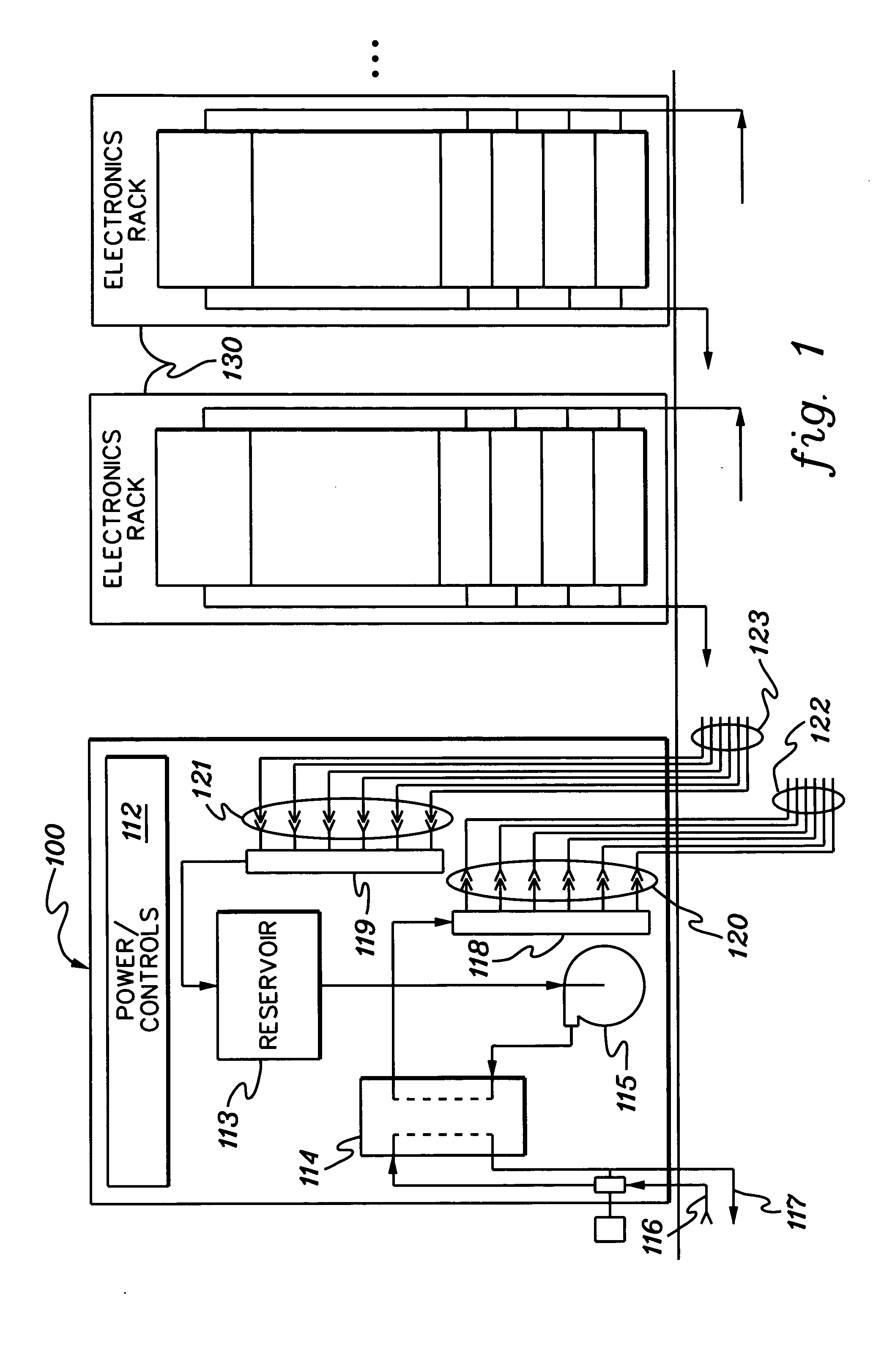
[0023] As used herein “electronics subsystem” comprises any housing, frame, rack, compartment, etc., containing one or more heat generating components of a computer system or other electronics system requiring cooling. The term “electronics rack” includes any frame or rack having a heat generating component of a computer system or electronics system; and may be, for example, a stand alone computer processor having high, mid or low end processing capability. In one embodiment, an electronics rack may comprise multiple electronics drawers, each having one or more heat generating components requiring cooling.

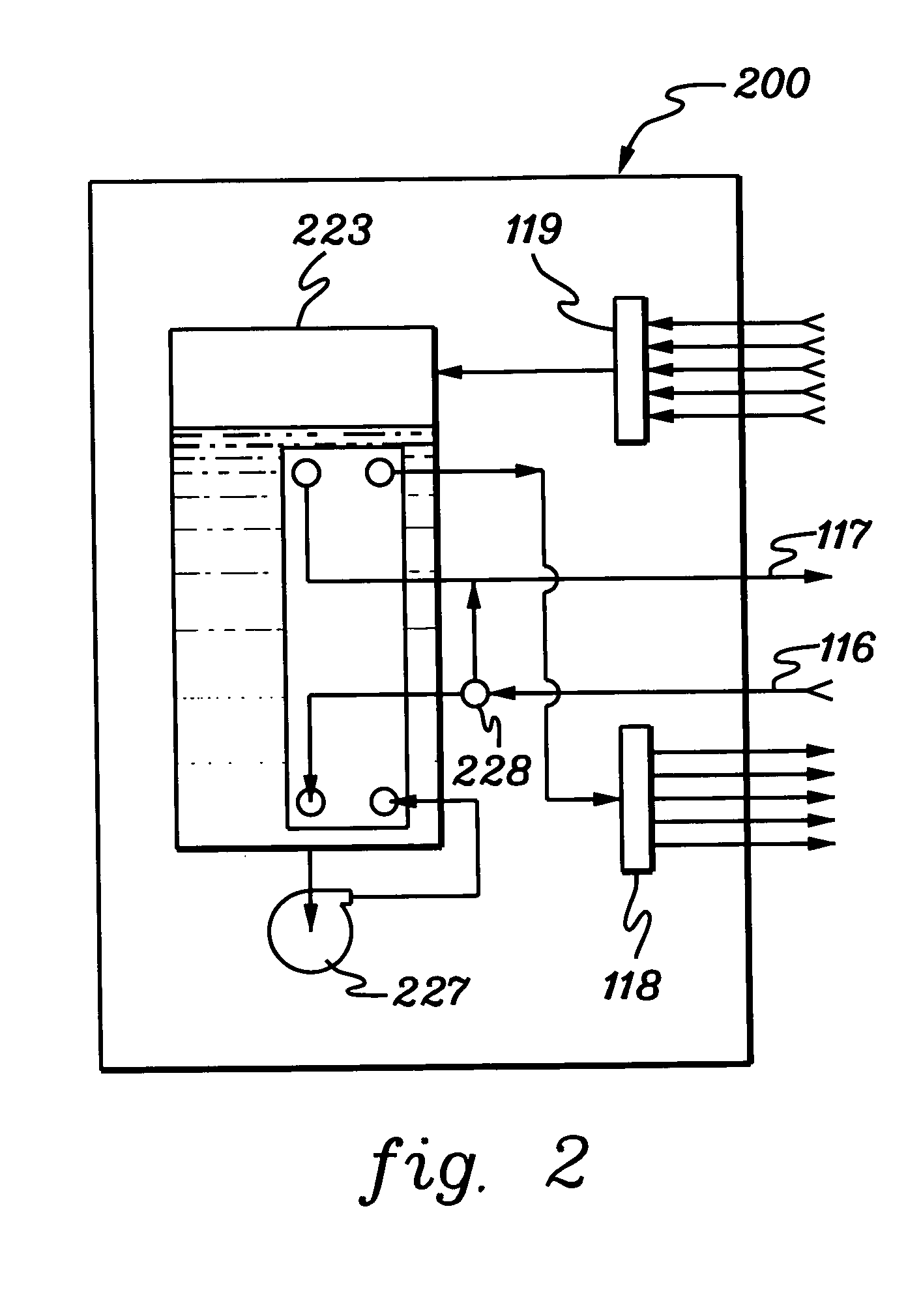
[0024] One example of coolant within the coolant distribution unit is water. However, the concepts disclosed are readily adapted to use with other types of coolant on both the facility side and the system side. For example, the coolant may comprise a brine, a fluorocarbon liquid, or other similar chemical coolant or a refrigerant, while still maintaining the advantages and unique ...


PUM


Abstract

Method, system and program product are provided for monitoring coolant within a cooling system designed to provide system coolant to one or more electronics subsystems. The monitoring technique includes employing at least one pressure transducer to obtain multiple pressure measurements related to an amount of coolant within an expansion tank of the cooling system, and determining a rate of volume change of coolant within the expansion tank employing the multiple pressure measurements. Successive pressure measurements can be taken at a known time interval to determine the rate of volume change of coolant within the expansion tank. An automatic determination can also be made on the immediacy of action to be taken for service of the cooling system based on the rate of volume change of coolant within the expansion tank.

Description

CROSS REFERENCE TO RELATED APPLICATIONS [0001] This application contains subject matter which is related to the subject matter of the following applications, each of which is assigned to the same assignee as this application and each of which is hereby incorporated herein by reference in its entirety: [0002]“Method, System and Program Product For Automatically Checking Coolant Loops Of A Cooling System For A Computing Environment,” Chu et al., (Docket No. POU920030164US1), Ser. No.______ , co-filed herewith; and [0003]“Scalable Coolant Conditioning Unit with Integral Plate Heat Exchanger / Expansion Tank and Method of Use,” Chu et al., Ser. No. 10 / 243,708, filed Sep. 13, 2002.TECHNICAL FIELD [0004] The present invention relates in general to cooling assemblies and other apparatus used for removing heat from electronic devices, modules and systems. More particularly, this invention relates to methods and systems for monitoring a rate of volume change of coolant within a cooling system ...

Claims


Application Information

Patent Timeline
Patent Type & Authority Applications(United States)
IPC IPC(8): G01F1/00G01F23/18G01F23/74G06F1/20
CPCG01F1/007G01F23/18G01F23/74H05K7/2079G06F1/206G06F2200/201G06F1/20
Inventor CHU, RICHARD C.ELLSWORTH, MICHAEL J. JR.SCHMIDT, ROGER R.SIMONS, ROBERT E.ZOODSMA, RANDY J.
Owner IBM CORP
Why Eureka
Try Eureka