
User interaction and operation-parameter determination system and operation-parameter determination method

a user interaction and operation parameter technology, applied in the field of user interaction systems and methods, can solve the problems of inability to notify users about the type of input (speech, push buttons), difficulty in system notification to users about when and what type of data,

Inactive Publication Date: 2005-06-02
CANON KK
View PDF9 Cites 10 Cited by
  • Summary
  • Abstract
  • Description
  • Claims
  • Application Information

AI Technical Summary

Benefits of technology

[0022] Further, the present invention is directed to provide an electronic system, a speech-synthesis system, and an interaction system that are used for correctly notifying the user of the timing and type of input by using the operation parameter determined based on the interaction state.
[0023] According to the present invention, an operation parameter based on the state of an interaction with an outside source can be provided. Further, users can be correctly notified about the timing and type of input by using the operation parameter that was determined based on the state of the interaction with the outside source.

Problems solved by technology

Although, the “system-initiative” interaction system can lead an interaction, it is difficult for the system to notify the user about when (and what type of data) should be input.
Accordingly, the following input errors often occur: (1) the user fails to input data because the user does not realize the system is finished; (2) the user inputs data before the system is finished; (3) after being asked to input data, the user may be organizing the user's thoughts and may input unrecognizable words such as “uh”, “well”, and so forth or the user may need to cough, etc.
However, these conventional []systems are unable to resolve all of the above-mentioned disadvantages.
Another disadvantage of conventional systems is that they cannot notify users about the type of input (speech, push buttons, and so forth) that can be processed by such systems.

Method used


Image

  • User interaction and operation-parameter determination system and operation-parameter determination method
  • User interaction and operation-parameter determination system and operation-parameter determination method
  • User interaction and operation-parameter determination system and operation-parameter determination method

Examples


first embodiment

[0053] An example where the operation-parameter determination system 101 shown in FIG. 1 is used for a car-navigation system will now be described with reference to FIGS. 3 to 6.

[0054]FIG. 3 is a block diagram illustrating the configuration of a first embodiment of the present invention. In FIG. 3, a car-navigation system 401 including the operation-parameter determination system 101 is shown. FIG. 4 shows an example of the car-navigation system 401 and a GUI screen 405.

[0055] In this car-navigation system 401, an operation parameter transmitted from the operation-parameter determination system 101 is supplied to a display control unit 302 via the operation-parameter reception unit 103. In this embodiment, an inquiry signal is transmitted at regular intervals, so as to obtain operation parameters.

[0056] The display control unit 302 has the function of inputting image data such as map data transmitted from a navigation main body 301 and displaying the image data on the GUI screen ...

second embodiment

[0070] In a second embodiment of the present invention, an example speech-synthesis system using the operation-parameter determination system 101 shown in FIG. 1 will be described with reference to FIGS. 7 to 12.

[0071]FIG. 7 is a block diagram illustrating the second embodiment of the present invention. More specifically, this drawing shows the functional configuration of a speech-synthesis system 501 including the operation-parameter determination system 101 shown in FIG. 1.

[0072] The speech-synthesis system 501 further includes a speech-synthesis parameter reception unit 502 and an inquiry-signal transmission unit 504 that correspond to the operation-parameter reception unit 103 and the inquiry-signal input unit 104, respectively. The speech-synthesis system 501 further includes a text-information capturing unit 507 for capturing text information from outside the speech-synthesis system 501, a speech-synthesis data storage unit 503 for storing speech-synthesis data, a speech-syn...

third embodiment

[0092] In a third embodiment of the present invention, the operation-parameter determination system 101 shown in FIG. 1 is used for form inputting by using a GUI screen and speech.

[0093]FIG. 12 shows a general form input screen illustrating a predetermined task of the automatic ticket-reservation system in the second embodiment.

[0094] Where a form input screen 1001 is displayed, as shown in this drawing, the user can fill in spaces in the form by using a mouse and a keyboard or inputting speech data through a microphone.

[0095] Where the form input screen 1001 ready for the speech inputting is displayed, the user may keep vocalizing data that cannot be input thereto. Therefore, it is effective to inform the user about which data can be input by speech. In this drawing, an animated icon 1002 is displayed near each of spaces that are ready for speech inputting as of this point.

[0096] The form and motion of the animated icon 1002 is changed according to the state of an interaction w...


PUM


Abstract

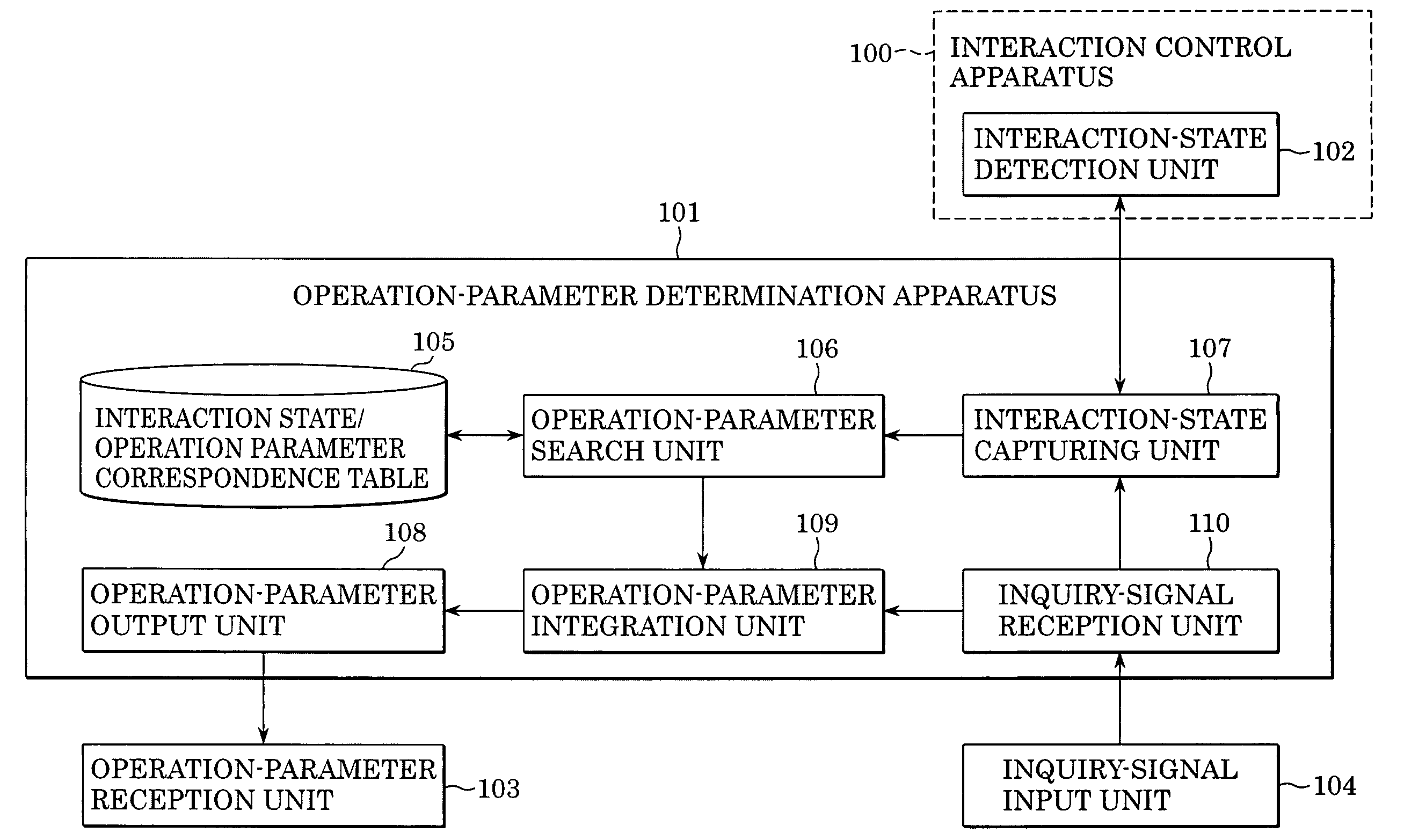
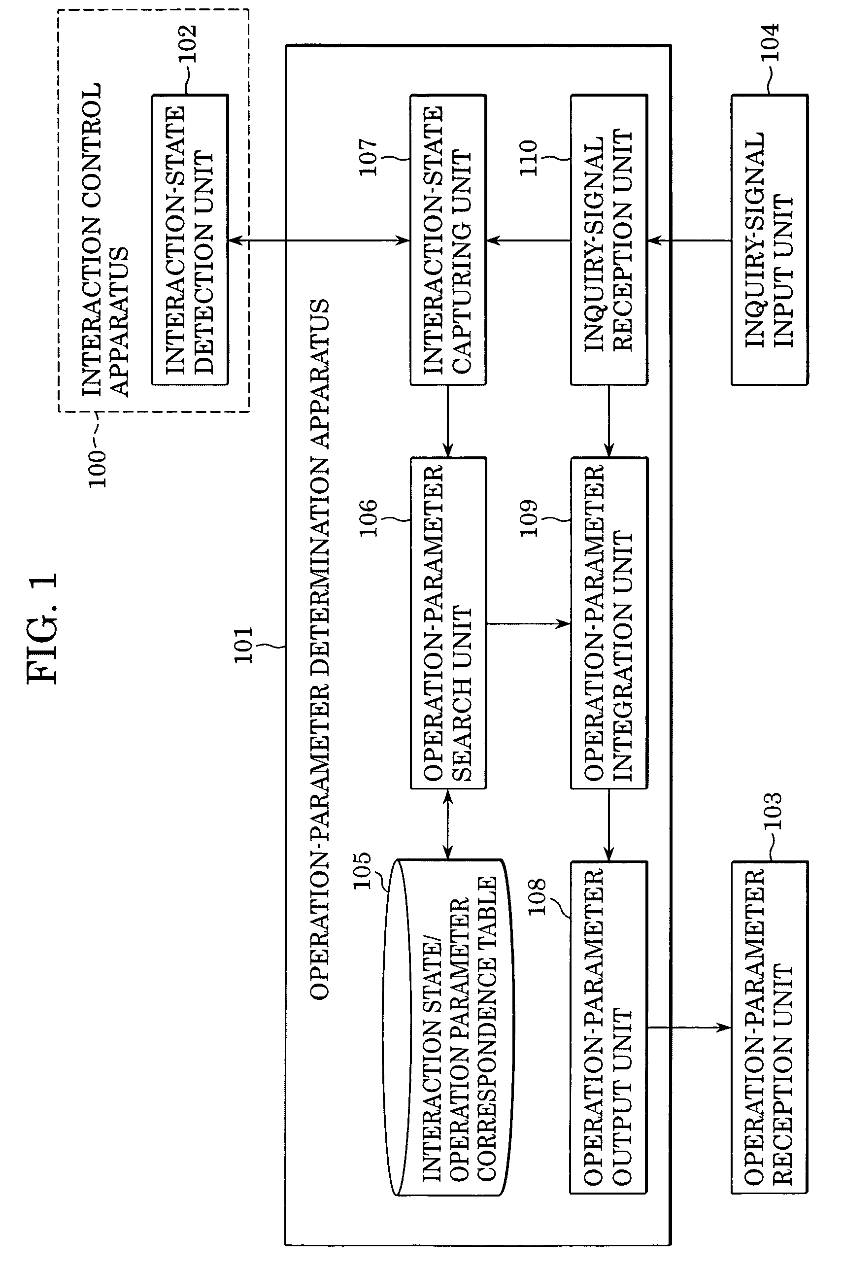
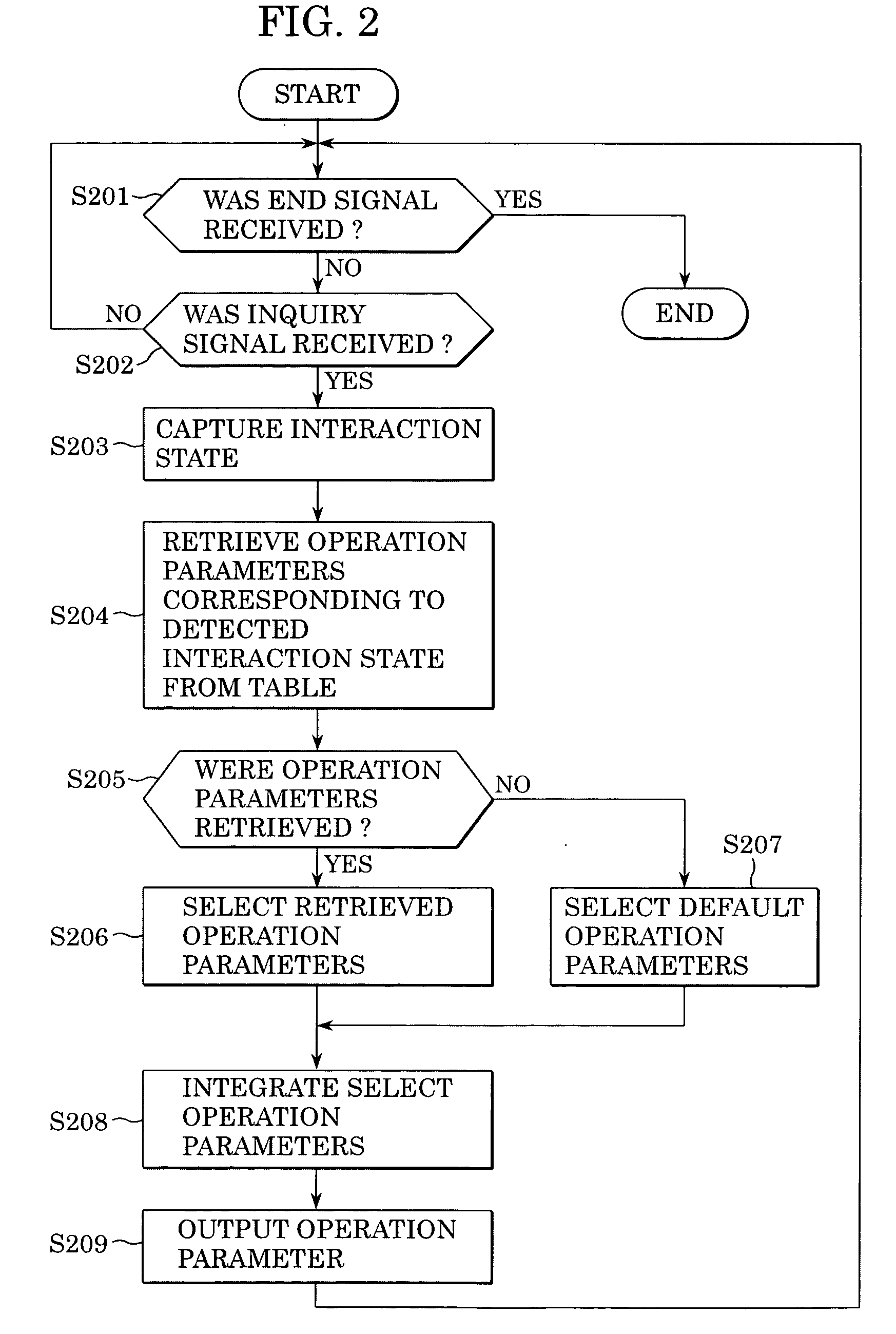
The present invention provides an interaction-state detection unit and an interaction-state capturing unit for detecting and capturing the current state of an interaction with a user. The present invention further provides a table storing interaction-state data and operation parameters that are paired with one another, an operation-parameter search unit for searching across the table based on the captured interaction state, an operation-parameter integration unit for generating at least one integrated operation parameter that resolves at least one contradiction between searched operation parameters, and an operation-parameter output part for outputting the integrated operation parameter generated by the operation-parameter integration unit.

Description

BACKGROUND OF THE INVENTION [0001] 1. Field of the Invention [0002] The present invention relates generally to user interaction systems and methods and more specifically to user interaction systems and methods for determining operation parameters. [0003] 2. Description of the Related Art [0004] Recently, speech-interaction systems have become more prevalent as standardization is achieved. Examples of such systems are car-navigation systems, automatic call centers and so forth. Recent speech interaction specifications such as VoiceXML have become standardized. See (http: / / www.w3.org / TR / voicexm120 / ) and Multimodal Interaction (http: / / www.w3.org / TR / mmi-framework / ), for example. [0005] The above-described interaction systems are referred to as “system-initiative” systems because they can lead users during an interaction. Such a system will typically ask questions to provide context so that users can reply. The following route-guidance system is an example, where S indicates a system out...

Claims


Application Information

Patent Timeline
IPC IPC(8): G06F3/16G06F7/00G06F17/30G10L13/00G10L13/04G10L13/08G10L13/10G10L15/00G10L15/22G10L15/28G10L21/10
CPCG10L13/033G06F17/30654G06F16/3329
Inventor NAKAGAWA, KENICHIROHIROTA, MAKOTOYAMAMOTO, HIROKI
Owner CANON KK
Learn More