Combustion chamber
- Summary
- Abstract
- Description
- Claims
- Application Information
AI Technical Summary
Benefits of technology
Problems solved by technology
Method used
Image
Examples
Example
DETAILED DESCRIPTION OF THE DRAWINGS
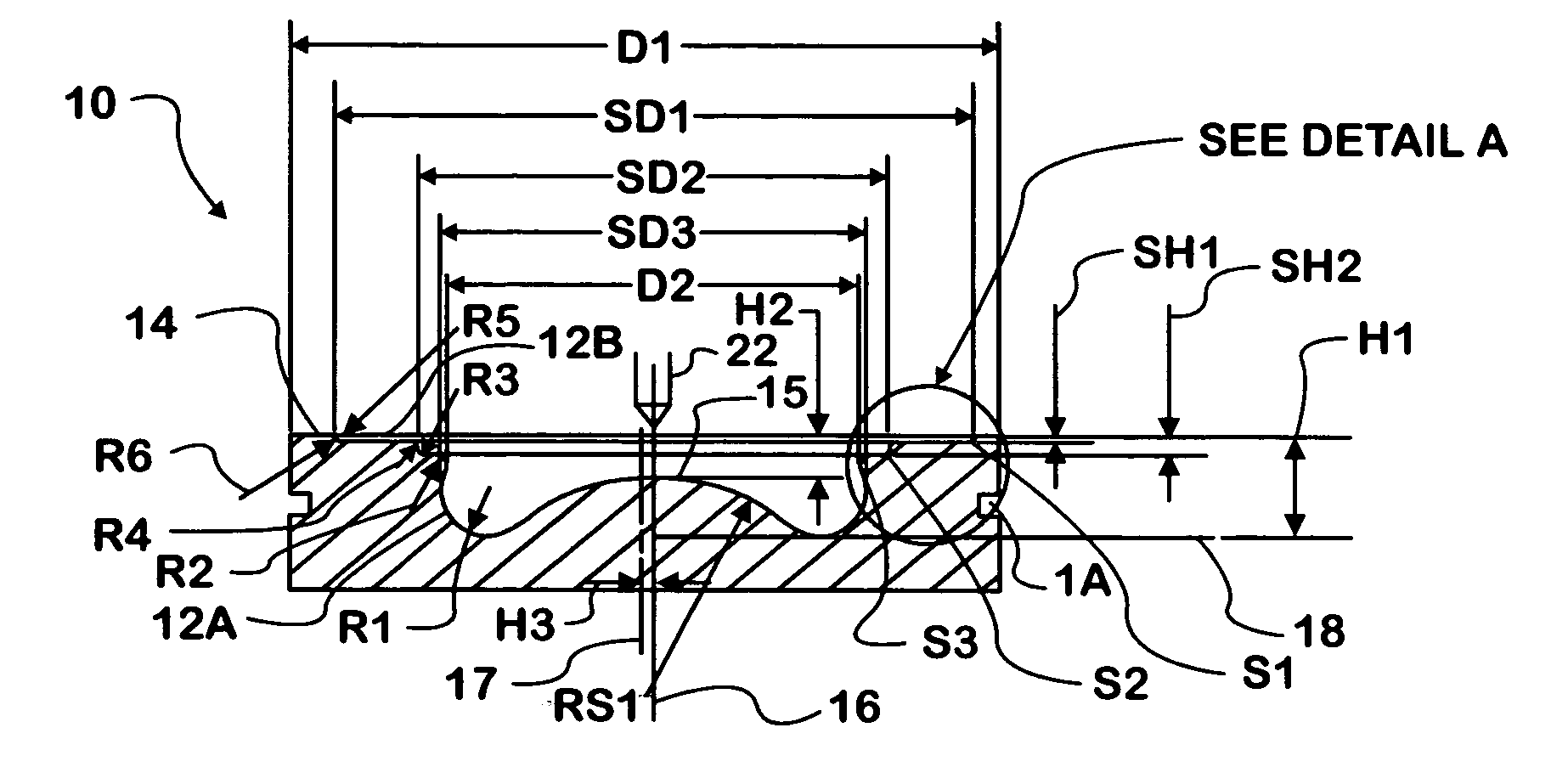
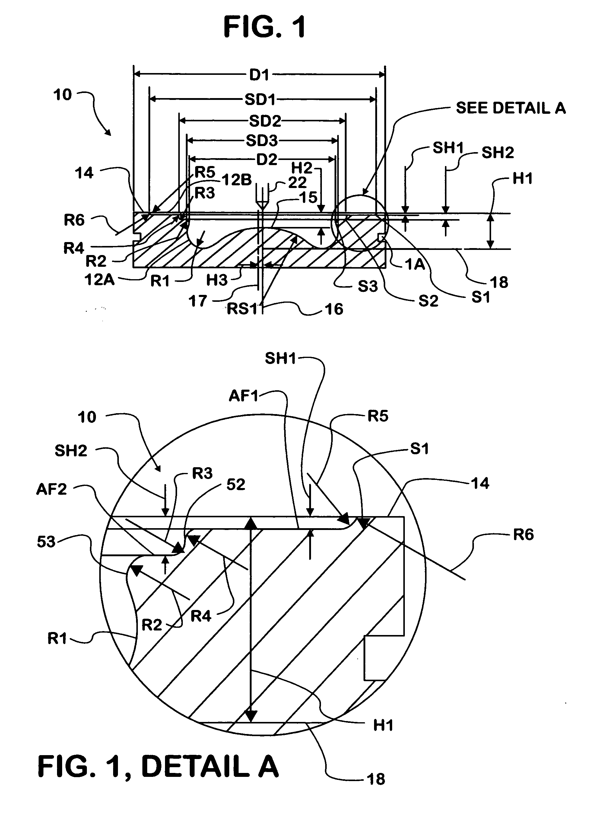
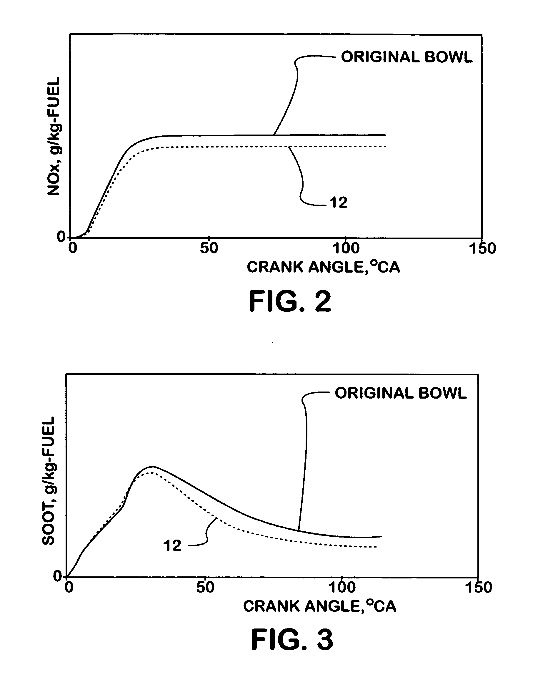
[0013] The piston of the present invention is shown generally at 10 in FIG. 1 and in more detail in FIG. 1a. Generally, the piston 10 has a centrally located symmetrical upward directed cavity for forming a portion of a combustion chamber 12 within a cylinder (not shown) of a diesel engine. The combustion chamber 12 is defined in the crown 14 of the piston 10. The engine has a fuel injector 22 for forming a fuel injection plume relative to the combustion chamber 12. The piston 10 may be utilized with two-valve or multiple-valve heads. It is desirable that the fuel be injected proximate the center of the piston 10 and that the injection pattern be radially symmetrical relative to the longitudinal chamber axis 16. The piston 10 is effective at reducing diesel engine pollutant emission, such as NOx and soot, as depicted in the graphic representations of FIGS. 2 and 3. The piston 10 is preferably applicable to heavy-duty and medium duty diesel engine...
PUM
 Abstract
Description
Claims
Application Information
 - R&D
- Intellectual Property
- Life Sciences
- Materials
- Tech Scout
- Unparalleled Data Quality
- Higher Quality Content
- 60% Fewer Hallucinations
Browse by: Latest US Patents, China's latest patents, Technical Efficacy Thesaurus, Application Domain, Technology Topic, Popular Technical Reports.
© 2025 PatSnap. All rights reserved.Legal|Privacy policy|Modern Slavery Act Transparency Statement|Sitemap|About US| Contact US: help@patsnap.com


