
Wavelength conversion apparatus

Inactive Publication Date: 2005-05-26
SANYO ELECTRIC CO LTD +1
View PDF5 Cites 24 Cited by
  • Summary
  • Abstract
  • Description
  • Claims
  • Application Information

AI Technical Summary

Benefits of technology

[0010] Additionally, in accordance with the wavelength conversion methods disclosed in Documents 1 and 2, the waveforms of the wavelength-converted signals deteriorate. Specifically, in Document 1, since a shape of signal spectrum corresponds to a spectrum shape of filter, a signal waveform remarkably depends on a spectrum shape of filter. Therefore, it is necessary to change a filter in accordance with signal bit rate or modulation method to be employed. On the other hand, in Document 2, since a saturated absorption due to electric carrier is used, the upper limit of response speed is restricted, and therefore a signal waveform is easily deteriorated when a high speed TDM signal conversion is carried out.
[0011] In order to overcome the above-mentioned problems, it is an object of the present invention to provide a wavelength conversion apparatus capable of making the wavelength of output light constant even when the wavelength of input light is changed, and to further provide an optical network system and an optical transmission system including such a wavelength conversion apparatus.
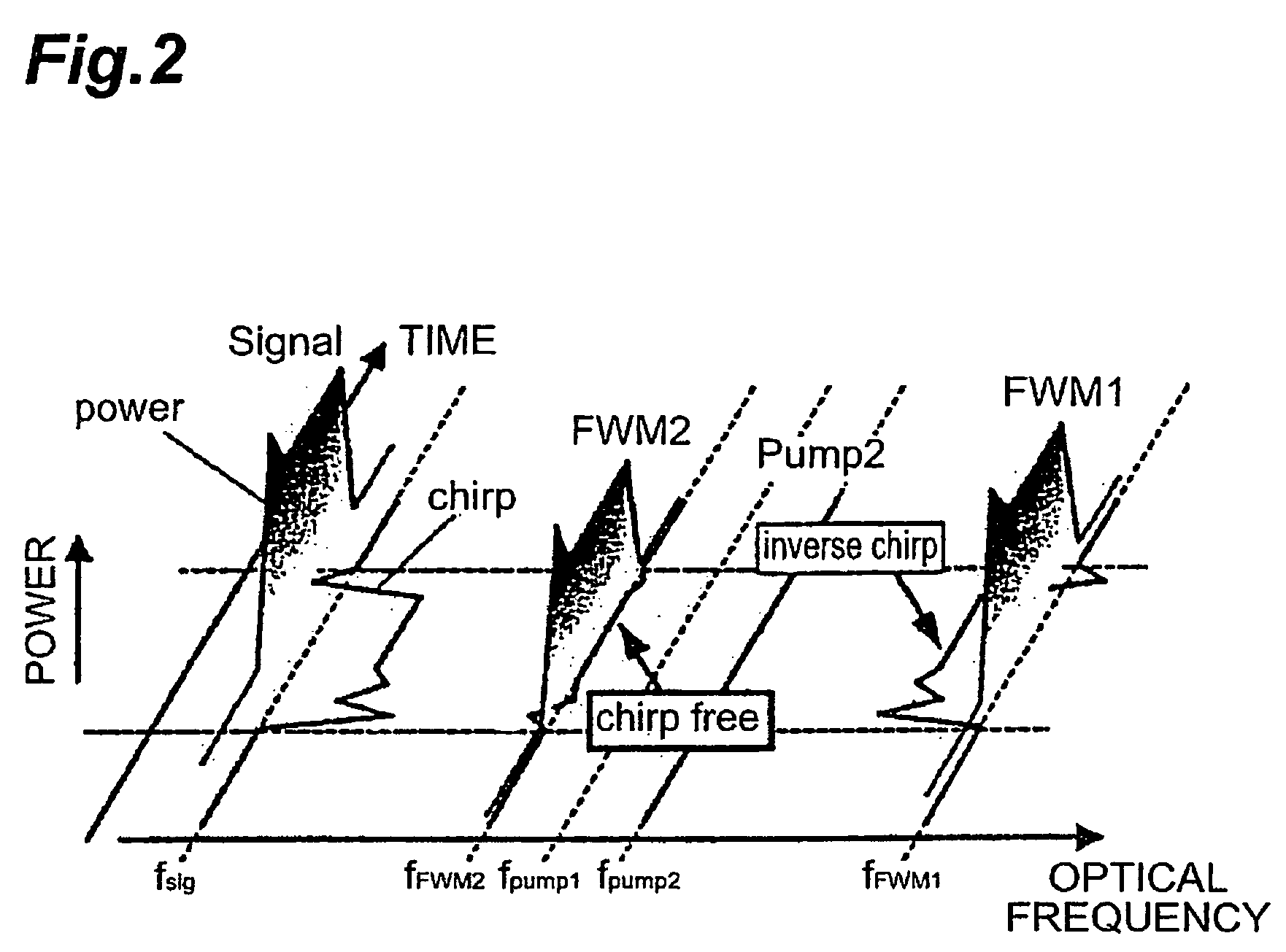
[0021] An optical transmission system according to the present invention comprises an optical transmitter, an optical transmission line, an optical receiver, and the above-mentioned wavelength conversion apparatus according to the present invention. The optical transmitter transmits light signals. The optical transmission line transmits the light signals transmitted from the optical transmitter. The optical receiver receives the light signals transmitted through the optical transmission line. In particular, the optical transmission system is characterized in that the wavelength conversion apparatus is provided just behind the optical transmitter. The wavelength conversion apparatus wavelength-converts the light signals transmitted from the optical transmitter. In the optical transmission system, even when the chirp of each light signal outputted from the optical transmitter is large or the extinction ratio thereof is low, the light signals outputted from the wavelength conversion apparatus is chirp-compensated and waveform-shaped, thereby allowing the transmission distance of the light signals to be extended.
[0022] Furthermore, in the optical transmission system according to the present invention, the above-mentioned wavelength conversion apparatus may be provided halfway in the optical transmission line. The wavelength conversion apparatus also wavelength-converts the light signals transmitted through the optical transmission line. In the optical transmission system, even when the chirp of the transmitted light is large or the extinction ratio thereof is low, the light outputted from the wavelength conversion apparatus is chirp-compensated and waveform-shaped, thereby allowing the transmission distance of the light to be extended.

Problems solved by technology

The inventors have studied conventional optical wavelength conversion apparatuses in detail, and as a result, have found problems as follows.
On the other hand, in Document 2, since a saturated absorption due to electric carrier is used, the upper limit of response speed is restricted, and therefore a signal waveform is easily deteriorated when a high speed TDM signal conversion is carried out.

Method used


Image

  • Wavelength conversion apparatus
  • Wavelength conversion apparatus
  • Wavelength conversion apparatus

Examples


first embodiment

[0063] (First Embodiment of Wavelength Conversion Apparatus)

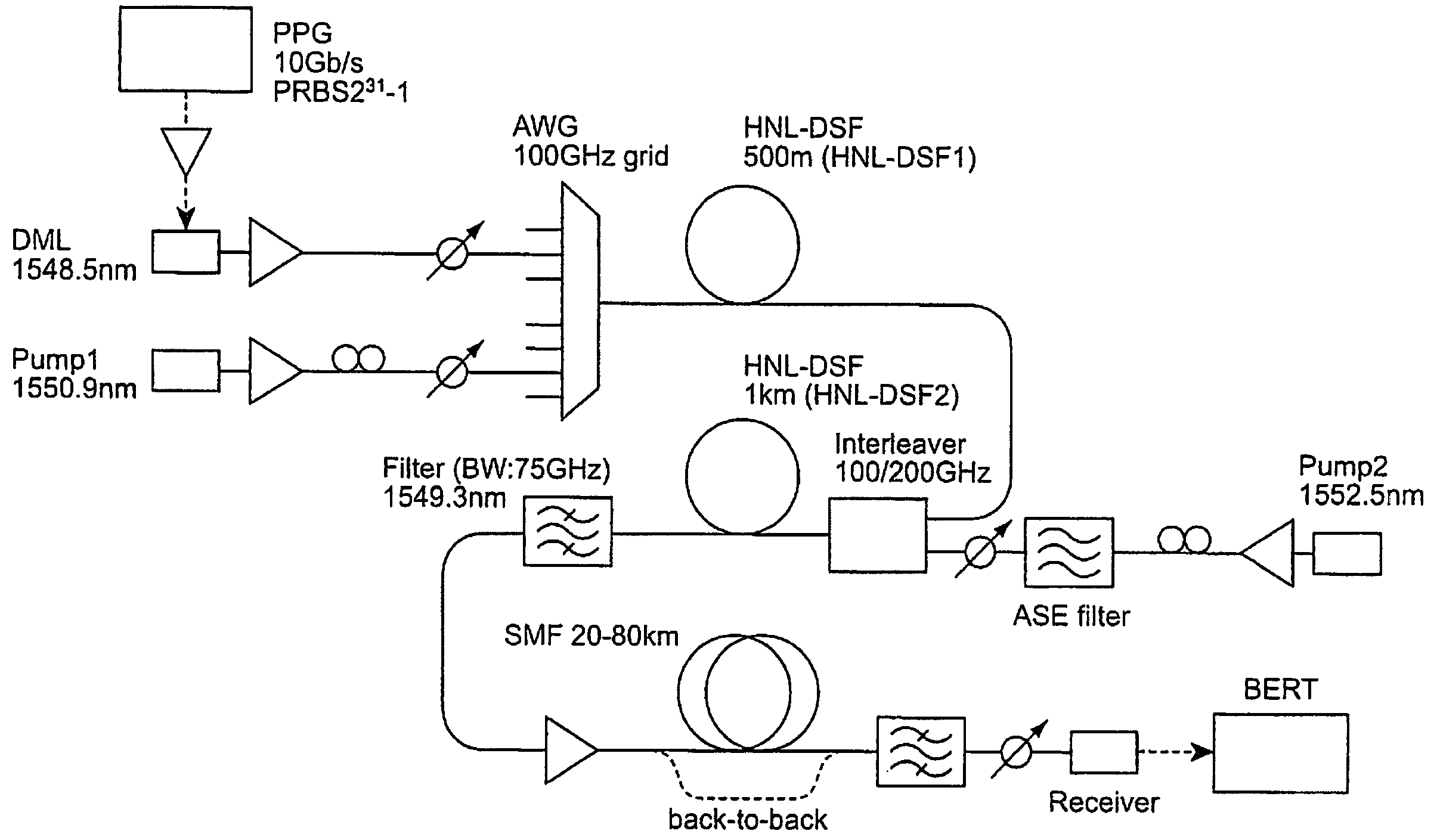
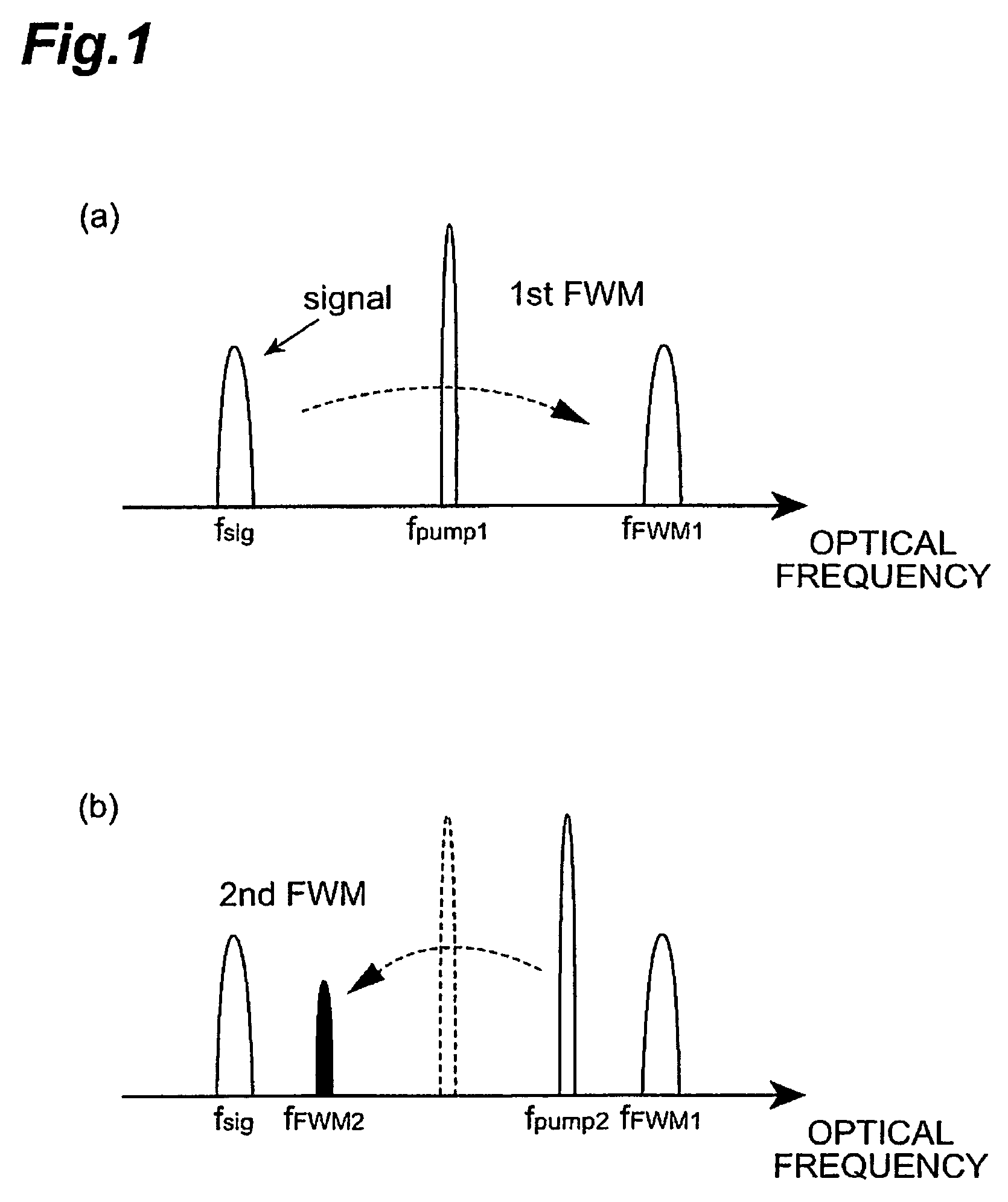
[0064] A first embodiment of a wavelength conversion apparatus according to the present invention will be described as follows. FIG. 10 is a diagram showing a configuration of a first embodiment of a wavelength conversion apparatus according to the present invention. The wavelength conversion apparatus 100 shown in FIG. 10 receives input light at its input end (incidence end) 101, to generates output light having a wavelength different from the wavelength of the input light, and output the generated output light from its output end (emission end) 102. The wavelength conversion apparatus 100 comprises a first wavelength converter 110 and a second wavelength converter 120 in series between the input end 101 and the output end 102.

[0065] The first wavelength converter 110 generates FWM by the input light and first pumping light, to generate intermediate light having a new wavelength by the FWM, and output the intermediate lig...

second embodiment

[0082] (Second Embodiment of Wavelength Conversion Apparatus)

[0083] A second embodiment of a waveform conversion apparatus according to the present invention will be then described. FIG. 14 is a diagram showing a configuration of a second embodiment of a wavelength conversion apparatus according to the present invention. The wavelength conversion apparatus 200 shown in FIG. 14 receives input light at its input end 201, to generate output light having a wavelength different from the wavelength of the input light, and output the generated output light from its output end 202. The wavelength conversion apparatus 200 comprises a first wavelength converter 210 and a second wavelength converter 220 in series between the input end 201 and the output end 202.

[0084] The first wavelength converter 210 generates FWM by the input light and first pumping light, to generate first intermediate light and second intermediate light each having a new wavelength by the FWM, and output the first interm...


PUM


Abstract

The present invention relates a wavelength conversion apparatus capable of making the wavelength of output light constant even when the wavelength of input light is changed. The wavelength conversion apparatus comprises a first wavelength converter and a second wavelength converter which are provided in series between an input terminal and an output terminal. The first wavelength converter generates four-wave mixing by input light and a first pumping light, generates an intermediate light having a new wavelength by the four-wave mixing, and outputs the intermediate light and the input light. The second wavelength converter generates four-wave mixing by the intermediate light and the input light, respectively outputted from the first wavelength converter, and a second pumping light, generates output light having a new wavelength by the four-wave mixing, and outputs the generated output light.

Description

CROSS-REFERENCE TO RELATED APPLICATION [0001] This application claims priority to Provisional Applications filed on May 12, 2004 and May 19, 2004, which are hereby incorporated by reference in its entirety.BACKGROUND OF THE INVENTION [0002] 1. Field of the Invention [0003] The present invention relates to a wavelength conversion apparatus for generating output light having a wavelength different from the wavelength of input light and outputting the generated output light, and an optical network system and an optical transmission system including such a wavelength conversion apparatus. [0004] 2. Related Background Art [0005] A wavelength conversion apparatus can generate output light having a different wavelength (i.e., a different optical frequency) from the wavelength of input light and output the generated output light. Generally, in a wavelength conversion apparatus, the input light and pumping light are inputted to a nonlinear optical medium, to generate four-wave mixing (FWM) w...

Claims


Application Information

Patent Timeline
IPC IPC(8): G02F1/35H01S3/10H04J14/02
CPCG02F1/3536H04J14/0223G02F2201/16
Inventor TANAKA, MASATO
Owner SANYO ELECTRIC CO LTD
Learn More