
Filtering of dynamic flows

a dynamic flow and filtering technology, applied in the field of filtering dynamic flows, can solve the problems of increasing the importance the possibility of attackers establishing fraudulent or misbehaving communication to a user's terminal, and the increase of security issues in communication networks, so as to achieve the effect of short-term deploymen

Active Publication Date: 2005-05-26
RPX CORP
View PDF6 Cites 68 Cited by
  • Summary
  • Abstract
  • Description
  • Claims
  • Application Information

AI Technical Summary

Benefits of technology

The present invention provides a solution for problems associated with dynamic pinholes in communication networks. The invention provides an alternative to existing solutions that have drawbacks. The invention involves creating an anchor node in the network and establishing bindings for terminals based on their addresses. The anchor node requests a binding for a terminal upon receiving a communication session request from a communication management node. The binding request is forwarded to the communication management node, which acknowledges the request and informs the first terminal of the session's initiation. The method allows for a short term deployment and is free from the drawbacks of existing solutions. The invention also provides a secure and authorized anchor for communications, ensuring appropriate security levels.

Problems solved by technology

In connection with such communication networks or network systems, respectively, security issues become more and more important.
Unused addresses or even port numbers, however, constitute a possibility for attackers to establish a fraudulent or misbehaving communication to a user's terminal who does not actually wish to have such a communication.
Therefore, security issues in communication networks become more and more important.
However, there is no way for the firewall FW to determine when the pinholes should be closed (since UDP communication does not have a session establishment / tear down as TCP does).
Such method however presents two major problems: (1) the user equipment UE does not have any knowledge concerning timers of the state created in the firewall FW and (2) this may result in a high number of bytes to be sent over the wireless link, thus wasting resources.
This, however, requires SIP signaling to be visible at the firewall, while, however, SIP compression may be applied (e.g. in 3GPP and 3GPP2 IMS) and the firewall FW may not be capable to decompress it.
Finally, this solution cannot be applied when IPsec (Internet Protocol (IP) security) or TLS (transport layer security) encryption is applied to protect the SIP.
Moreover, although this solution allows for the control to be in a manufacturer's products (e.g. SIP server), the deployment is not fully independent from products from other companies.
These methods are however still individual drafts and it will take a very long time before such solutions will become standardized.

Method used


Image

  • Filtering of dynamic flows
  • Filtering of dynamic flows
  • Filtering of dynamic flows

Examples


Embodiment Construction

[0090] The present invention will now be described in detail with reference to the accompanying drawings.

[0091] For the purpose of the illustration of this invention, a SIP call with real-time streams is described. However, the method described in this document is not restricted to scenarios where SIP is used (e.g. 3GPP IMS) but may also be applied e.g. in WAP scenarios. Generally, it can also be applied in any other working environment where dynamic pinholes need to be created but firewall configuration interfaces are not present.

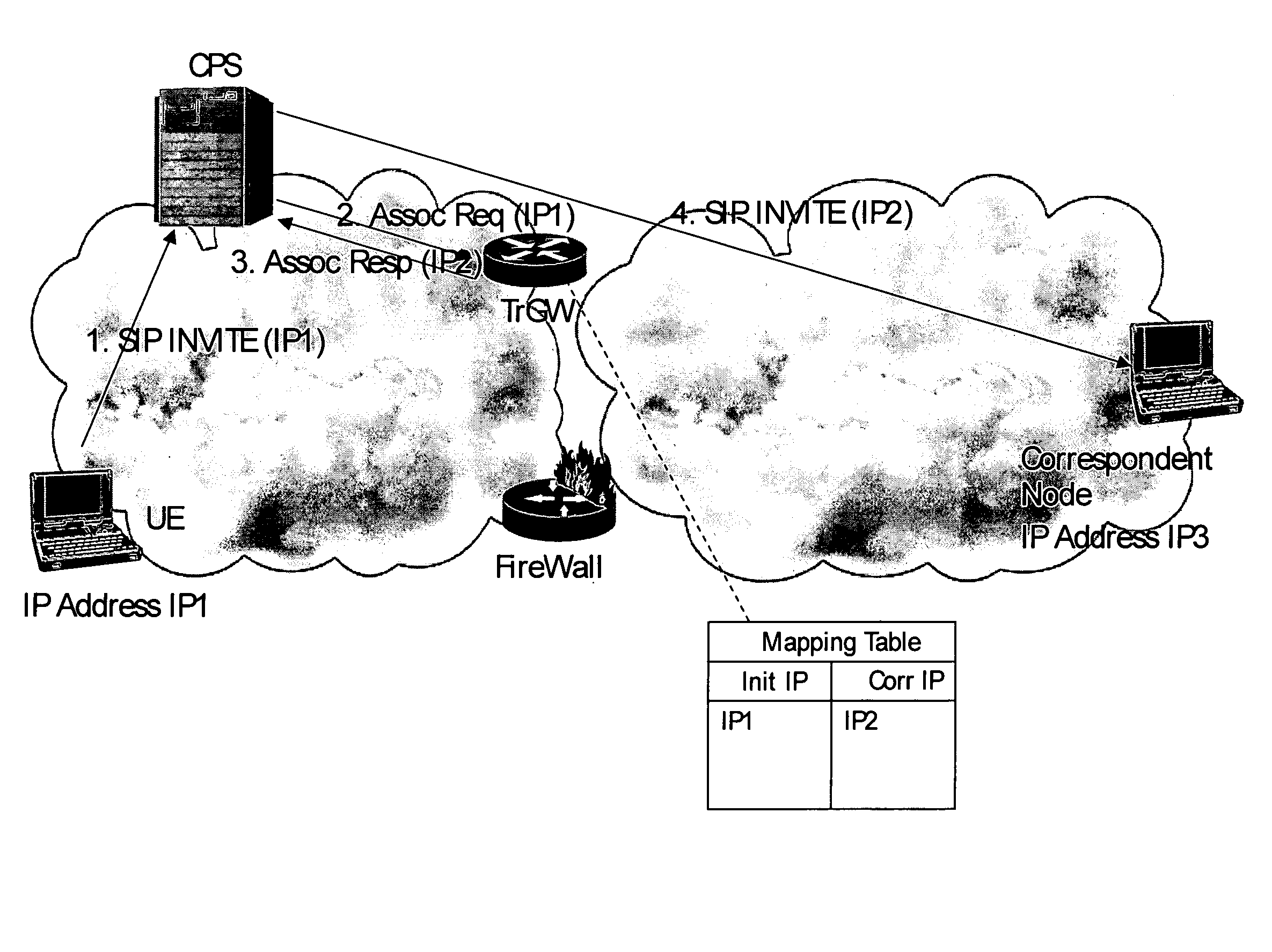
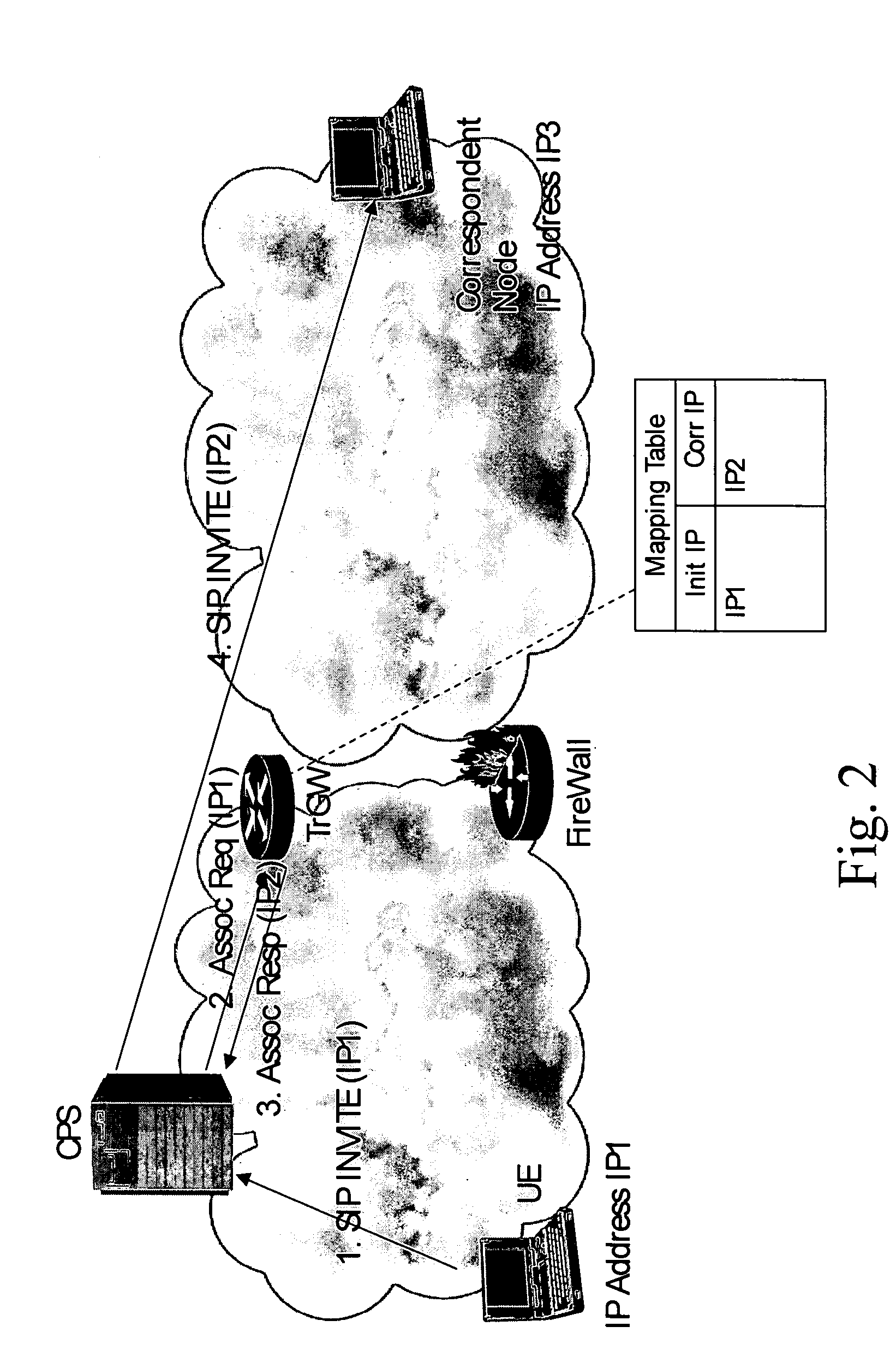
[0092] It will be recognized that the invention makes use of an anchor node such as a Translator Gateway (TrGW). The functionality of the anchor node is to switch the addresses such as IP addresses in the IP header according to the stored IP Mapping Table; its functionality is similar to the one of a network address translator NAT. Also, it will be seen that the invention makes use of an interface between the CPS (or a SIP proxy) and the TrGW. This inter...


PUM


Abstract

Methods and correspondent nodes to filter IP communications through firewalls in scenarios where dynamic pinholes are created to ensure an appropriate level of security is disclosed. The invention is based on creating a secure and authorized anchor for communications where all the communications are routed through before a firewall performs the packet filtering. A Translator Gateway (TrGW) switches addresses in the header according to a stored Mapping Table and an interface between a CPS (or a SIP proxy) and the TrGW. This interface allows the CPS to request the TrGW to provide bindings data between IP addresses upon session initiation, the TrGW to provide the bindings data to the CPS and the CPS to release the bindings at session release. The firewall accepts incoming packets whose IP address belongs to the pool of addresses of the TrGW. Thus any incoming packet that does not correspond to an existing call will be dropped at the TrGW, and a valid packet will go through the firewall which will verify that the packet is not a malformed message or other attack.

Description

REFERENCE TO RELATED APPLICATIONS [0001] This application claims priority of U.S. Provisional Patent Application Ser. No. 60 / 524,640, filed on Nov. 25, 2003, the contents of which are hereby incorporated by reference.FIELD OF THE INVENTION [0002] The present invention relates to the filtering of dynamic flows, and more particularly, to a filtering node, an anchor node used in connection with the filtering, a method for configuring such an anchor node, and a corresponding method of communicating data. BACKGROUND OF THE INVENTION [0003] Recently, communication networks have widely spread and are used in every day life by many users. Among such communication networks, so-called packet switched communication networks find increasing attention. Packet switched networks transmit / receive data in units of packets. A packet consists of a header carrying control information such as (among others) for example a packet's address information (source / destination) as well as of a payload section c...

Claims


Application Information

Patent Timeline
Patent Type & Authority Applications(United States)
IPC IPC(8): H04L12/24H04L29/06H04L29/12H04M7/00
CPCH04L29/12009H04L29/1233H04L29/12358H04L29/12547H04L41/0604H04L65/1006H04L61/2582H04L63/0209H04L63/0254H04L63/029H04L65/1016H04L61/251H04L61/00H04L61/25H04L65/1104H04L12/28
Inventor LE, FRANKFACCIN, STEFANO
Owner RPX CORP
Learn More