Swelling layer inflatable
- Summary
- Abstract
- Description
- Claims
- Application Information
AI Technical Summary
Benefits of technology
Problems solved by technology
Method used
Image
Examples
Embodiment Construction
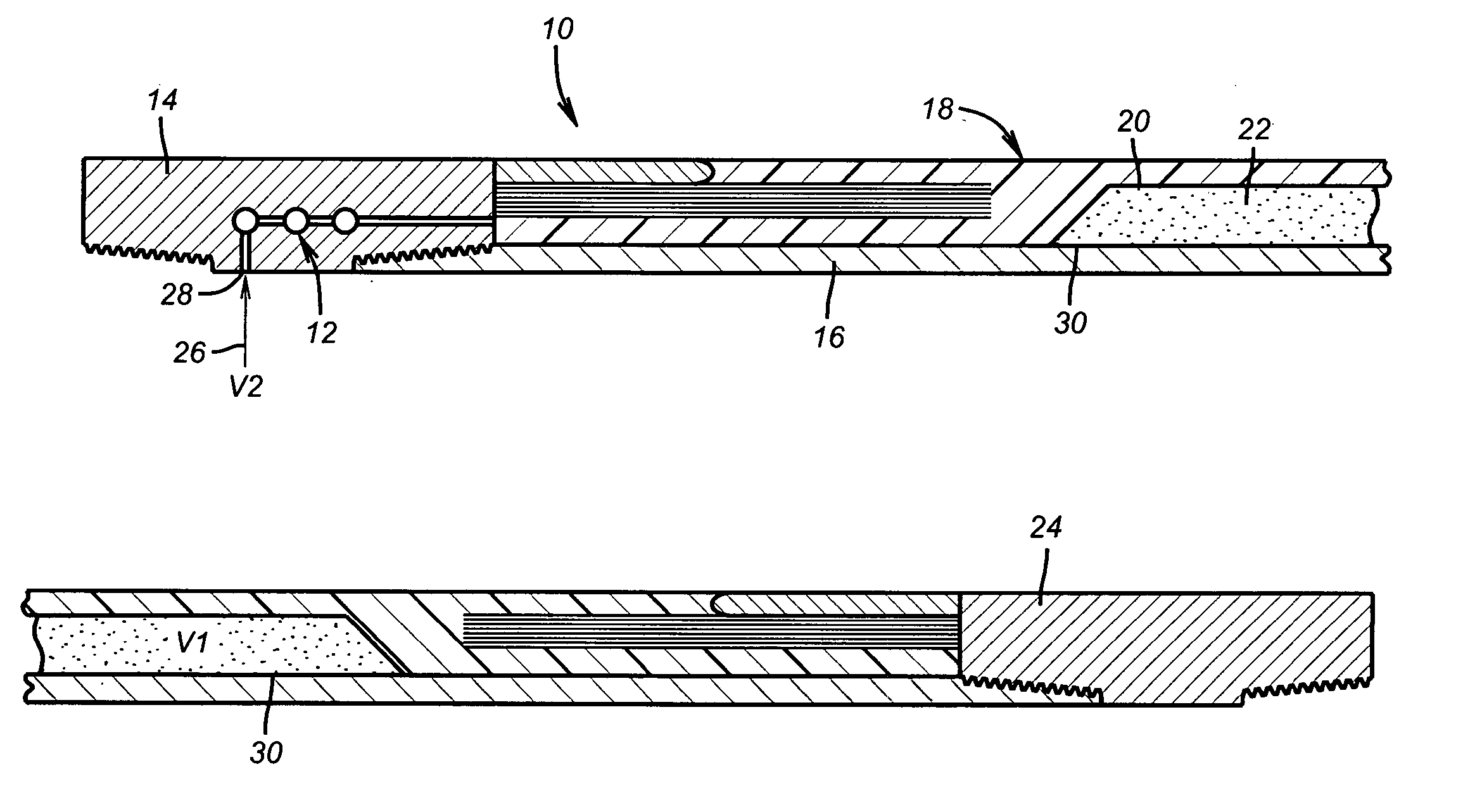
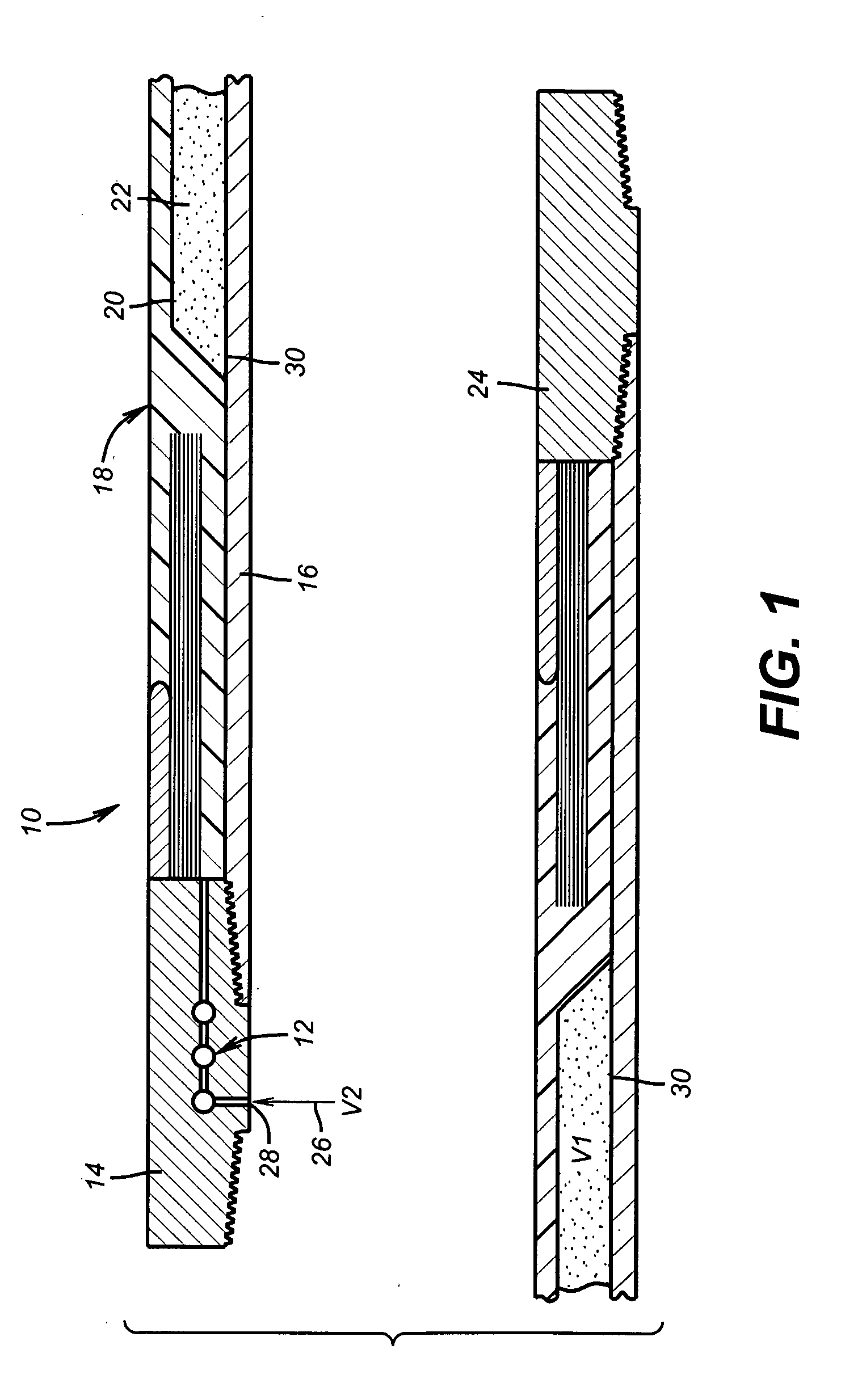
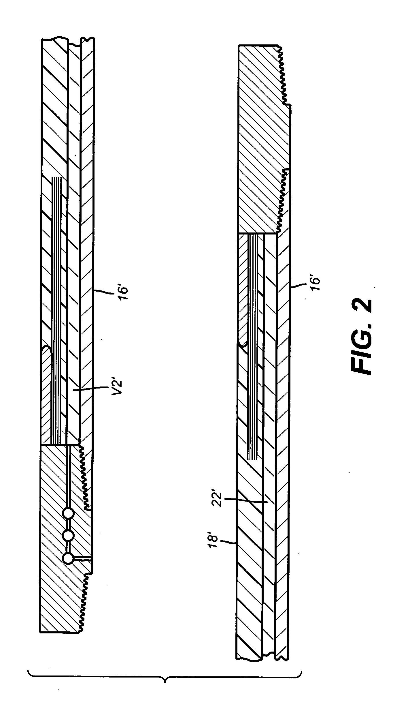
[0013]FIG. 1 schematically shows an inflatable packer 10 is section. It has a known inlet valve assembly 12 on a stationary collar 14 connected to mandrel 16. The inflatable element 18 has attached to an inner surface 20 a swelling layer 22. Schematically illustrated at the lower end of the element 18 is lower collar 24. Inflation fluid, shown schematically as arrow 26 is pumped into inlet 28. As shown in FIG. 1, the swelling layer has an initial volume V1. A predetermined volume V2 also schematically represented in FIG. 1 is pumped into inlet 28. The fluid volume is absorbed into the volume V1 of the swelling layer. In the preferred embodiment, the swelling layer 22 swells as it absorbs at least some of the fluid volume V2. In the preferred embodiment the final volume V3, shown in FIG. 4, is at least as large and preferably larger than the sum of V1 and V2 prior to mixing the inflation fluid, represented by arrow 26 with the swelling layer 22. The inflation fluid 26 first contacts ...
PUM
 Abstract
Description
Claims
Application Information
 - R&D
- Intellectual Property
- Life Sciences
- Materials
- Tech Scout
- Unparalleled Data Quality
- Higher Quality Content
- 60% Fewer Hallucinations
Browse by: Latest US Patents, China's latest patents, Technical Efficacy Thesaurus, Application Domain, Technology Topic, Popular Technical Reports.
© 2025 PatSnap. All rights reserved.Legal|Privacy policy|Modern Slavery Act Transparency Statement|Sitemap|About US| Contact US: help@patsnap.com


