Gliding submersible transport system

Inactive Publication Date: 2005-05-26
THE BOEING CO
View PDF7 Cites 24 Cited by
  • Summary
  • Abstract
  • Description
  • Claims
  • Application Information

AI Technical Summary

Benefits of technology

[0009] Embodiments of the present invention provide a gliding submersible transport system. Exemplary embodiments provide submersible gliders having wings capable of providing sufficiently high lift-to-drag ratios such that the submersible gliders of the present invention may be used for transporting large volumes of military or commercial hardware, equipment, personnel, or the like.
[0011] According to an aspect of this embodiment of the present invention, the lifting surface is an “arch wing” with a box plane-like design that provides a higher effective aspect ratio than a planar wing with a comparable planform. As a result, higher lift and greater hydrodynamic efficiency (that is, to lift-to-drag ratio) are generated than in a corresponding planar wing. Extended stepwise glide ranges result from use of the arch-wing. The submersible glider gradually buoys to the surface under controlled ballasting and repeatedly glides forward along a glide path slope determined by the lift-to-drag ratio. Advantageously, the submersible glider of this embodiment of the present invention may slowly and quietly transport heavy payloads including special supplies, sensor platforms, ordnance, and heavy equipment as desired, such as an unmanned aerial vehicle (UAV).
[0013] According to an aspect of this embodiment of the present invention, a surfaced glider defines a hold that may be configured as a personnel cabin for surfaced transport of personnel. Advantageously, the personnel are housed in the surfaced glider that is designed to float and travel along the sea surface. The surfaced glider may be “self-towed” forward to the submersible glider after the submersible glider buoys to the surface. As a result, personnel may be transported in a relatively safe and stealthy manner. Use of the surfaced glider to transport personnel avoids risks and extreme costs incurred with transport of personnel in a submerged glider. Advantageously, use of the surfaced glider avoids complex underwater life-support and emergency escape systems for submerged transport of personnel.

Problems solved by technology

However, currently known unmanned delivery vehicles produce large amounts of noise.
As a result, currently known delivery vehicles may not bring significant amounts of stealth to a tactical situation.
Accordingly, effectiveness of currently known delivery vehicles may be diminished.
Once the glider attains its desired depth, internal air volume of the glider is increased, thereby lowering its density.
However, currently known gliders have limited glider range and applicability.
Because of the Seaglider's limited speed and glide capabilities, the Seaglider is limited to oceanographic research.
However, internal capacities of currently known gliders are limited due to extensive components for ballasting and steering.

Method used


Image

  • Gliding submersible transport system
  • Gliding submersible transport system
  • Gliding submersible transport system

Examples


Embodiment Construction

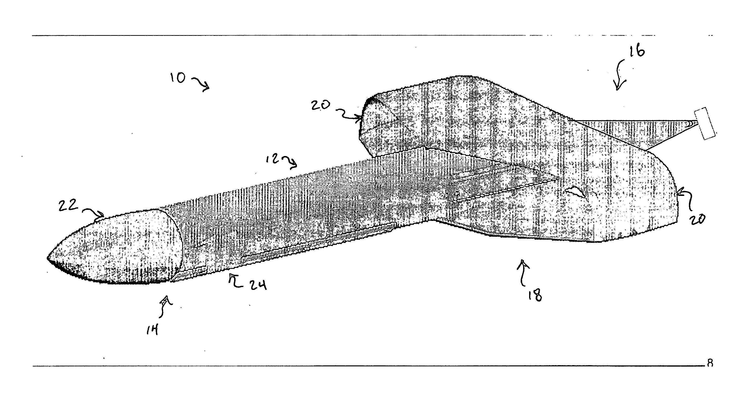
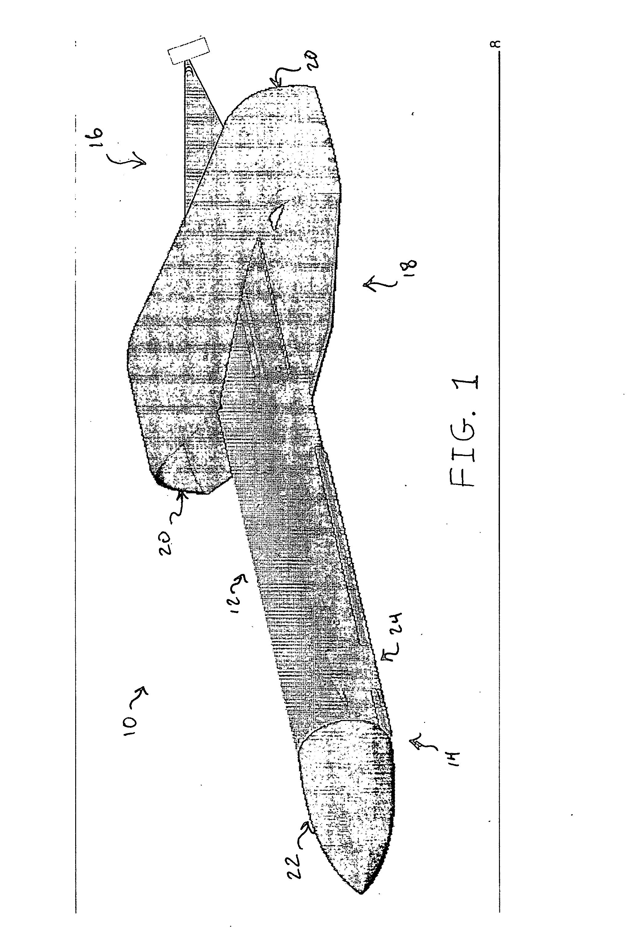
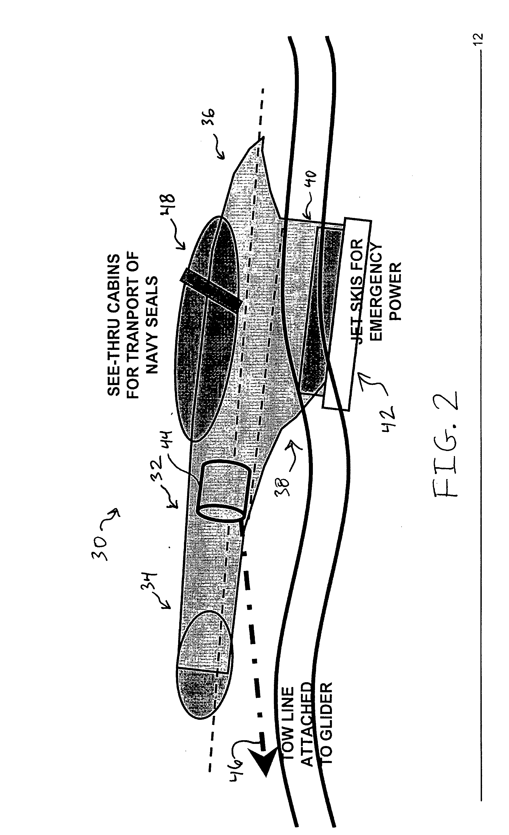
[0038] By way of overview, embodiments of the present invention provide a gliding submersible transport system. Exemplary embodiments provide submersible gliders having wings capable of providing sufficiently high lift-to-drag ratios such that the submersible gliders of the present invention may be used for transporting large volumes of military or commercial hardware, equipment, personnel, or the like. According to one exemplary embodiment of the present invention, a submersible glider has a step-wise glider range. The glider includes a substantially cylindrical hull having a bow and a stern. A generally planar lifting surface is disposed toward the stern. The lifting surface has a pair of generally planar stabilizer surfaces that extend generally perpendicular to a plane of the lifting surface from ends of the lifting surface. A nose cone and at least one steering device are disposed toward the bow. According to another embodiment of the present invention, a marine transport syste...


PUM


Abstract

Embodiments of the present invention provide a gliding submersible transport system. Exemplary submersible gliders have wings capable of providing sufficiently high lift-to-drag ratios such that the submersible gliders of may be used for transporting large volumes of military or commercial hardware, equipment, personnel, or the like. According to one exemplary embodiment of the present invention, a submersible glider has a step-wise glider range. The glider includes a substantially cylindrical hull having a bow and a stern. A generally planar lifting surface is disposed toward the stern. The lifting surface has a pair of generally planar stabilizer surfaces that extend generally perpendicular to a plane of the lifting surface from ends of the lifting surface. A nose cone and at least one steering device are disposed toward the bow.

Description

FIELD OF THE INVENTION [0001] The present invention relates generally to submersible vehicles and, more specifically, to submersible gliders. BACKGROUND OF THE INVENTION [0002] Marine vessels have long been used for commercial and military purposes. For example, commercial ships transport goods and tourists. As another example, military surface ships project power and deliver ordnance to targets, deliver military supplies and logistics, and transport military personnel. Further, military submarines deliver ordnance to targets and provide strategic deterrence from stealthy platforms. Finally, civilian and military marine vessels engage in scientific research of the ocean environment. [0003] In some applications, it would be desirable to accomplish some of the objectives listed above through use of unmanned marine vessels. For example, use of an unmanned marine vessel to deliver ordnance, such as a torpedo, to a target would permit the ordnance to be delivered to the target without pu...

Claims


Application Information

Patent Timeline
IPC IPC(8): B63G8/00B63G8/14B63G8/18
CPCB63G8/001B63G8/18B63G8/14
Inventor AUGUST, HENRY
Owner THE BOEING CO
Why Eureka
Try Eureka