
Method and apparatus for magnetic actuation of variable pitch impeller blades

a variable-pitch impeller and magnetic actuator technology, which is applied in the direction of rotors, special-purpose vessels, vessel construction, etc., can solve the problems of affecting the operation of the blade control motor, and the level of control is not generally available from the conventional control fin assembly, so as to achieve the elimination of mechanical linkages between the impeller and the blade control motor.

Inactive Publication Date: 2005-05-19
THE BOEING CO
View PDF15 Cites 4 Cited by
  • Summary
  • Abstract
  • Description
  • Claims
  • Application Information

AI Technical Summary

Benefits of technology

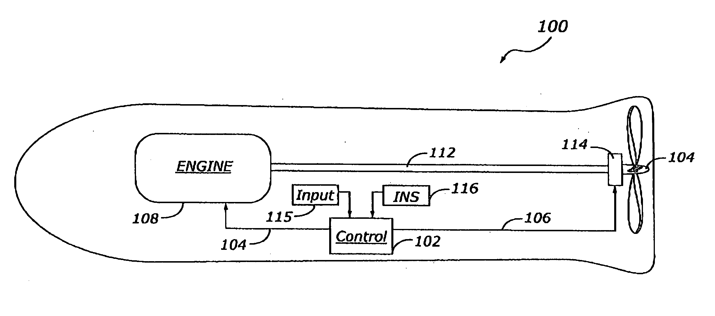
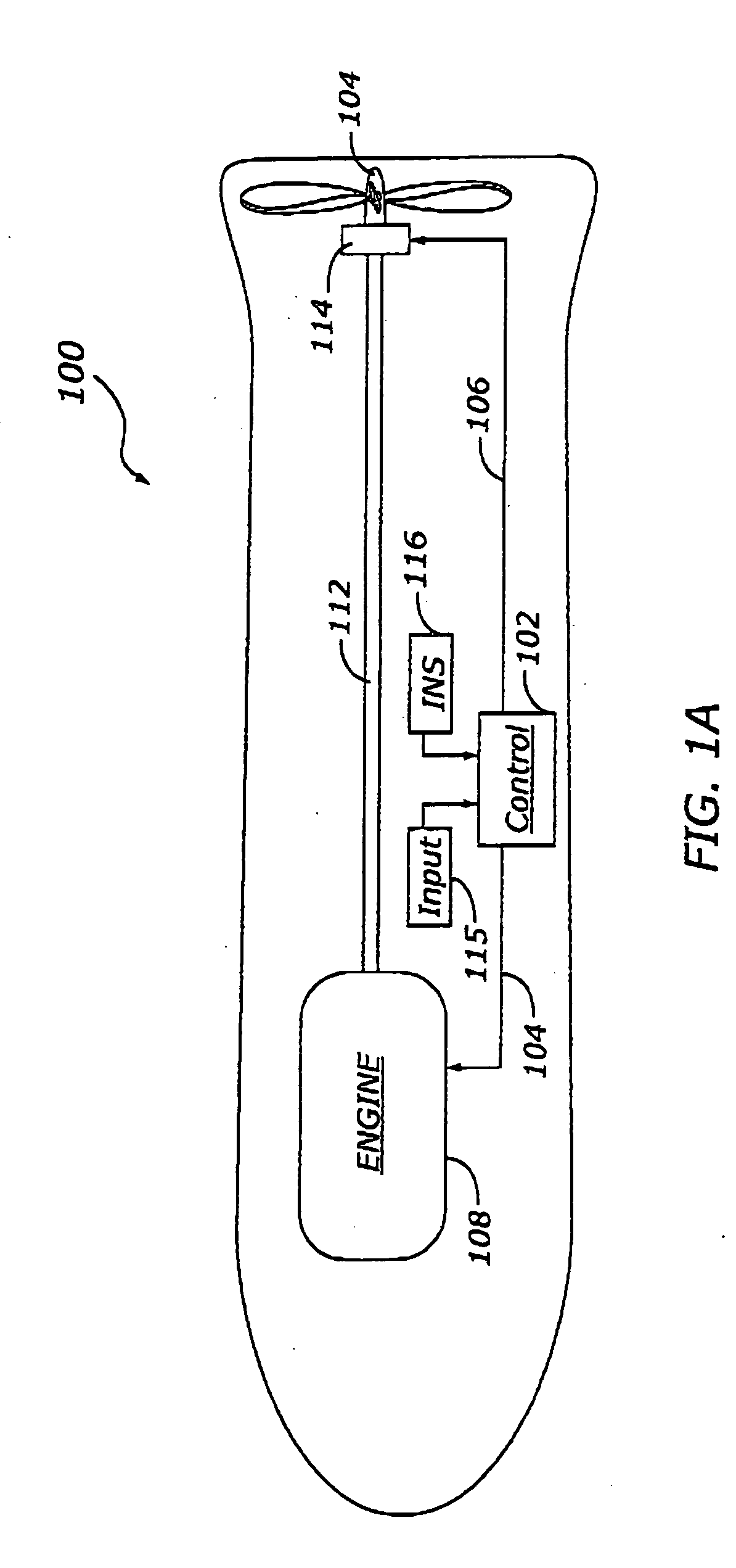
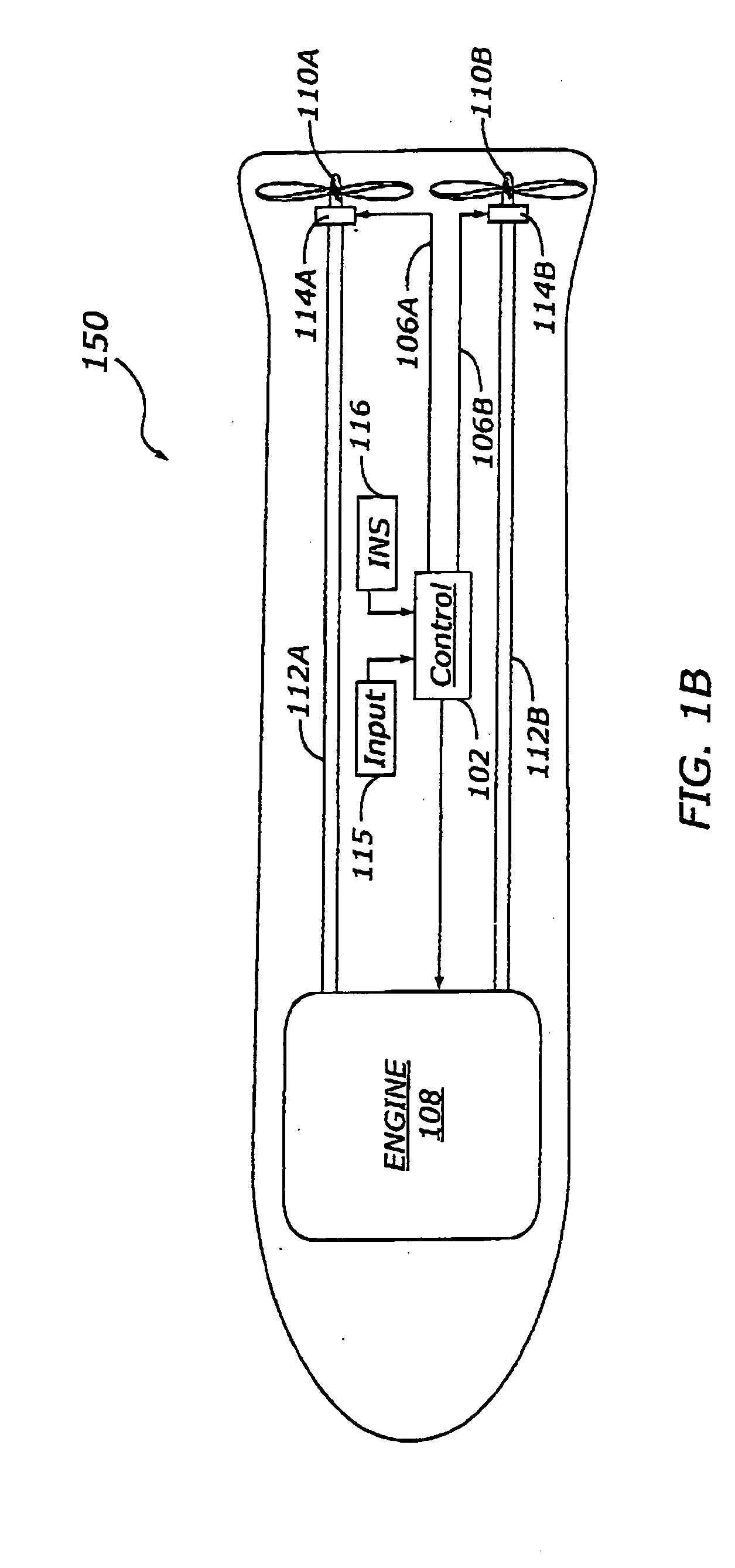
The patent describes an integrated propulsion and guidance system for a vehicle that uses magnetic actuators to adjust the pitch of control blades on an impeller. This system allows for precise control of the vehicle's orientation and direction through the use of the impeller. The use of magnetic actuators eliminates the need for mechanical linkages between the impeller and the blade control motor, making the system more efficient and reliable.

Problems solved by technology

At present, however, the full potential of UUVs is limited by the propulsion and control systems currently available for such devices.
For very slow-moving systems, for example, very precise control is typically desired, yet this level of control is not generally available from conventional control fin assemblies.
Moreover, conventional fin assemblies typically jut out from the body of the vehicle, and may therefore be susceptible to breakage or deformity when the UUV is deployed in highly-demanding environments (e.g. from the air or a submarine) if the fins are not sufficiently reinforced.
Further, fin assemblies tend to be less precise when operating in reverse, thereby limiting the maneuverability of the vehicle, particularly at low speeds.
Other problems associated with various conventional fin assemblies include cost, mechanical complexity, excess acoustic noise, control authority and survivability.

Method used


Image

  • Method and apparatus for magnetic actuation of variable pitch impeller blades
  • Method and apparatus for magnetic actuation of variable pitch impeller blades
  • Method and apparatus for magnetic actuation of variable pitch impeller blades

Examples


Embodiment Construction

[0016] The following detailed description is merely exemplary in nature and is not intended to limit the invention or the application and uses of the invention. Furthermore, there is no intention to be bound by any expressed or implied theory presented in the preceding technical field, background, brief summary or the following detailed description.

[0017] According to various exemplary embodiments, a control system and method for a vehicle operating in a fluid medium (e.g. water, air) uses the propulsion element (e.g. impeller or propeller) of the vehicle to produce guidance force as well. By selectively adjusting the pitch angle of propulsion blades as they rotate through the fluid medium, the relative forces and moments produced by the various blades can be manipulated to produce torques on the vehicle driveshaft that can be used to position the vehicle. One or more impeller blades, for example, can be actuated in a sinusoidal or sawtooth manner such that one period of actuation ...


PUM


Abstract

An integrated propulsion and guidance system for a vehicle includes an engine coupled to an impeller via a driveshaft to produce propulsive force. The impeller includes a hub and a plurality of blades, including at least one control blade pivotably mounted to the hub. A control system provides a control signal to a magnetic actuator to adjust the blade pitch of the control blades as the blades rotate about the hub. The magnetic actuator provides an electromagnetic field that interacts with a magnet coupled to the control blade to adjust the pitch of the control blade. The change in blade pitch produces a torque on the driveshaft that can be used to control the heading of the vehicle. By varying the magnitude and phase of the control signal provided to the impeller, the torque can be applied in a multitude of distinct reference planes, thereby allowing the orientation of the vehicle to be adjusted through action of the impeller. Moreover, because the control blades are actuated magnetically, mechanical linkages between the impeller and the blade control motor may be eliminated.

Description

TECHNICAL FIELD [0001] The present invention generally relates to vehicle propulsion systems, and more particularly relates to a magnetic actuator for a variable pitch impeller system that simultaneously provides propulsion and guidance to a vehicle. BACKGROUND [0002] Various types of manned and unmanned undersurface vehicles (UUVs) have been developed in recent years for military, homeland security, underwater exploration and other purposes. These devices tpically resemble a torpedo or small submarine, yet are typically capable of sophisticated underwater tasks including reconnaissance, ordnance neutralization, ship repair and the like. [0003] At present, however, the full potential of UUVs is limited by the propulsion and control systems currently available for such devices. For very slow-moving systems, for example, very precise control is typically desired, yet this level of control is not generally available from conventional control fin assemblies. Moreover, conventional fin a...

Claims


Application Information

Patent Timeline
Patent Type & Authority Applications(United States)
IPC IPC(8): B63G8/00B63G8/16B63H3/00B63H3/10B63H5/14F42B19/01F42B19/06F42B19/12F42B19/46
CPCB63G8/001B63G8/16B63H3/002B63H3/10F42B19/46F42B19/01F42B19/06F42B19/12B63H5/14
Inventor ATMUR, ROBERT J.SYDNOR, BRYAN J.
Owner THE BOEING CO
Learn More