Apparatus and method for receiving an OFDM signal

a technology of receiver and receiver, applied in the field of multicarrier radio transmission system, can solve the problems of poor accuracy, reduced receiving characteristic, and reduced channel estimation accuracy, and achieve the effect of improving channel estimation accuracy

Inactive Publication Date: 2005-05-19
KK TOSHIBA
View PDF1 Cites 21 Cited by
  • Summary
  • Abstract
  • Description
  • Claims
  • Application Information

AI Technical Summary

Benefits of technology

[0009] It is, therefore, an object of the present invention to provide apparatus and method for receiving an OFDM signal, which are capable of improving channel estimation accuracy even if variation between sub-carriers is large in a radio transmission channel.

Problems solved by technology

However, it is insufficient to only calculate a channel estimation value from the preamble signal; in this case, accuracy is worse, and also, receiving characteristic is reduced.
However, the channel estimation method has a problem that the channel estimation accuracy is reduced if the transmission channel variation between sub-carriers is large.
In this case, averaged vector receives the influence of sub-carrier having large amplitude; as a result, the phase difference between sub-carriers becomes non-uniform.

Method used


Image

  • Apparatus and method for receiving an OFDM signal
  • Apparatus and method for receiving an OFDM signal
  • Apparatus and method for receiving an OFDM signal

Examples


first embodiment

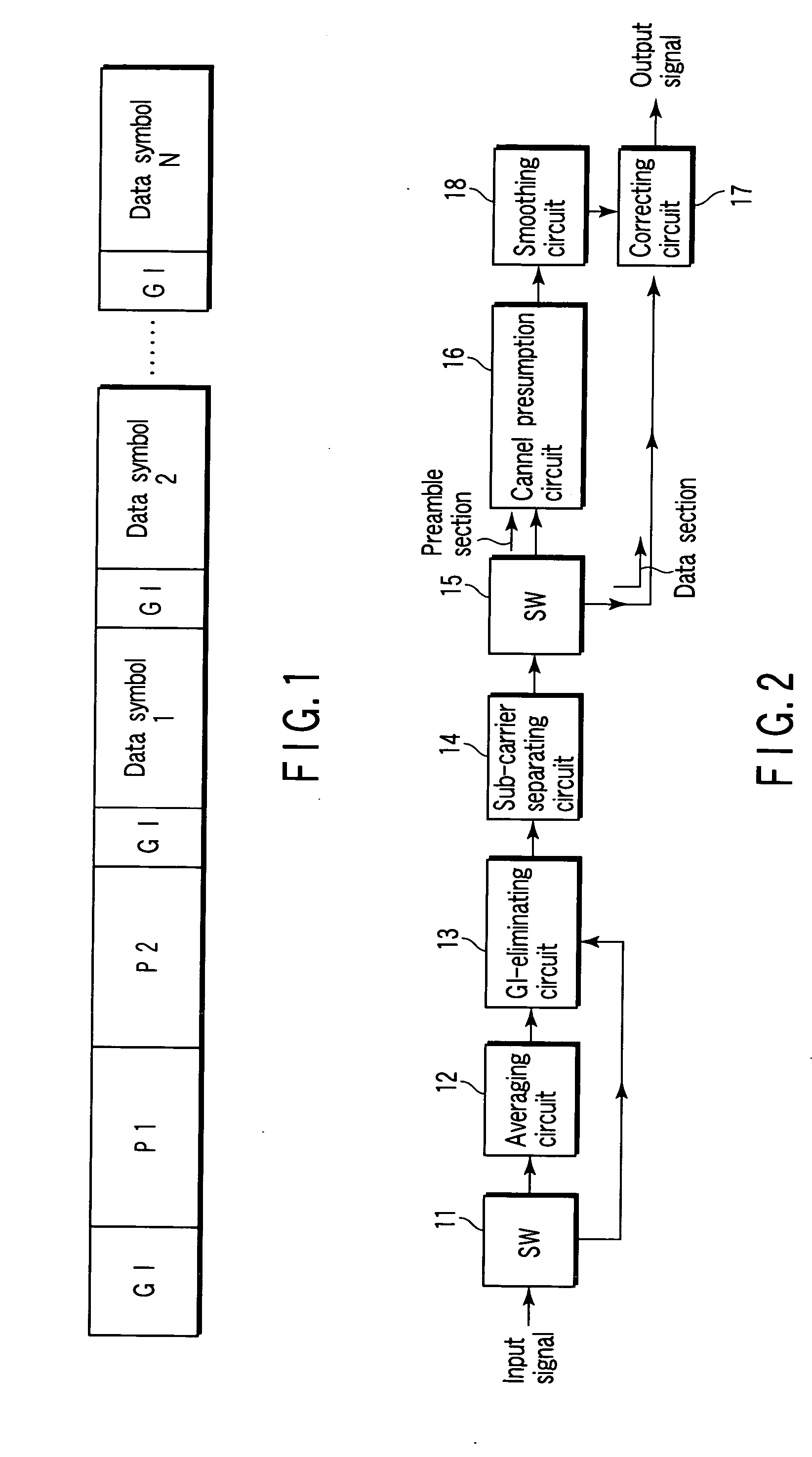
[0027] An OFDM radio transmission system according to one embodiment has estimation of handling a format signal shown in FIG. 1. According to format, two preamble signals (preambles P1 and P2) continuously appear in the leasing end of a transmission frame, that is, header area. The preamble signals each have known amplitude and phase characteristic for transmission channel response estimation. Guard interval GI is added to the front end of the preamble. Data area exists after guard interval GI at the back of the preamble P2. In the data area, pilot symbol having known amplitude and phase characteristic is not always inserted to all carriers.

[0028] Here, OFDM symbol is composed of n sub-carriers.

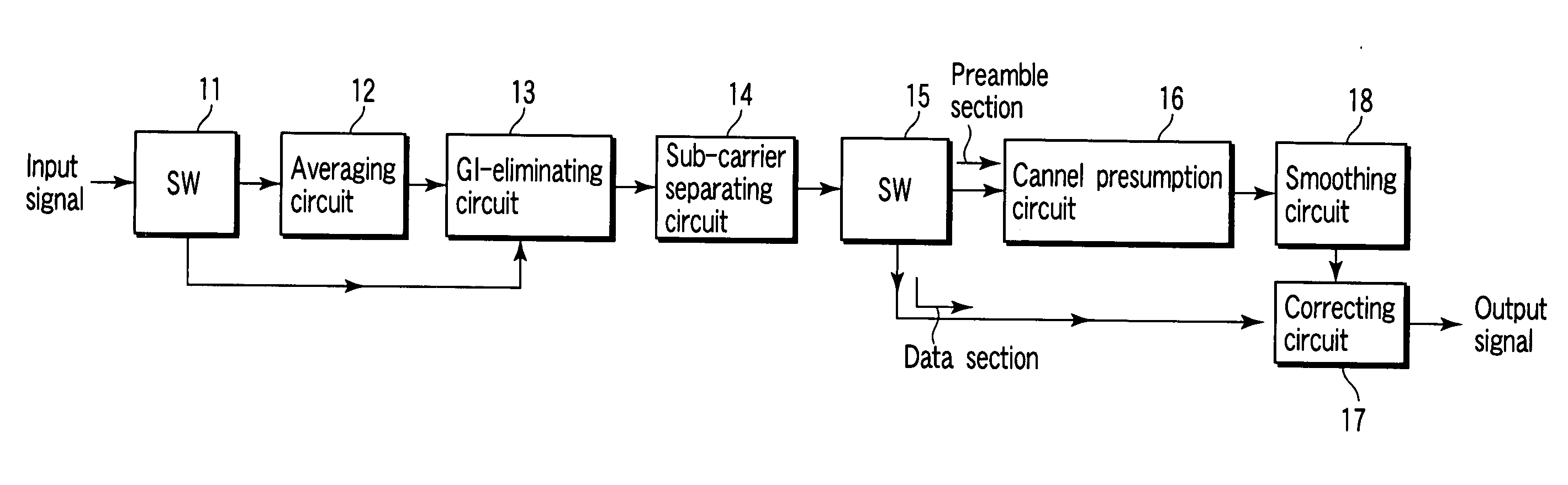
[0029]FIG. 2 is a block diagram showing the configuration of principal parts of a demodulator included in a receiver of the OFDM radio transmission system.

[0030] In FIG. 2, a received OFDM signal (hereinafter, referred to as received signal) is guided to the leading header area of the tran...

second embodiment

[0065]FIG. 11 is a block diagram showing the configuration of the smoothing circuit 18 according to a second embodiment of the present invention. In FIG. 11, the same reference numerals are used to designate parts identical to FIG. 4, and the details are omitted.

[0066] More specifically, a weight coefficient multiplier 211-1 to 211-3 is connected between the divider 183-1 to 183-3 and the vector combining circuit 184. A weight coefficient multiplier 212-1 to 212-3 is connected between the amplitude measuring circuit 182-1 to 182-3 and the average circuit 185.

[0067] The weight coefficient multiplier 211-1 to 211-3 multiplies the unit vector outputted from the divider 183-1 to 183-3 by a weight coefficient. The weight coefficient multiplier 212-1 to 212-3 multiplies the output of the amplitude measuring circuit 182-1 to 182-3 by a weight coefficient. The weight coefficient is set α for the value from the register 181-1, is set β for the value from the register 181-2, and is set α fo...


PUM


Abstract

An apparatus includes a converter separating the OFDM signal into the several sub-carriers, an extraction circuit extracting the reference symbol from at least one of a plurality of sub-carriers, an estimation circuit estimating a transmission distortion channel every the sub-carrier based on the amplitude and phase characteristic of the reference symbol, an adder adding channel estimation results of a first sub-carrier be set at least one of the plurality of sub-carriers, a second sub-carrier adjacent to a high-band side of the first sub-carrier and a third sub-carrier adjacent to a low-band side of the first sub-carrier, a calculator calculating the average of the added value to obtain amplitude and phase correction values with respect to the first sub-carrier, and a correction circuit correcting amplitude and phase with respect to each of the plurality of sub-carriers based on the amplitude and phase correction values.

Description

CROSS-REFERENCE TO RELATED APPLICATIONS [0001] This application is based upon and claims the benefit of priority from prior Japanese Patent Applications No. 2003-297816, filed Aug. 21, 2003; and No. 2004-232685, Aug. 9, 2004, the entire contents of both of which are incorporated herein by reference. BACKGROUND OF THE INVENTION [0002] 1. Field of the Invention [0003] The present invention relates to a multi-carrier radio transmission system such as OFDM (Orthogonal Frequency Division Multiplexing) radio transmission system. In particular, the present invention relates to apparatus and method for receiving an OFDM signal. [0004] 2. Description of the Related Art [0005] According to one of multi-carrier, that is, OFDM, information is transmitted using several sub-carriers orthogonal to each other. Under radio communication environment, amplitude and phase variations (distortion) occur in a received signal by Rayleigh fading and multi-path due to a change of relatively positional relati...

Claims


Application Information

Patent Timeline
IPC IPC(8): H04J11/00H04L25/02H04L25/03H04L27/26
CPCH04L25/0232H04L2025/03522H04L2025/03414H04L27/2647
Inventor MITSUGI, JUN
Owner KK TOSHIBA
Why Eureka
Try Eureka