
Footwear closure system with zonal locking

a closure system and shoe technology, applied in the field of footwear, can solve the problems of not being optimal or suitable for all applications, not being suitable for known locking systems, and not being suitable for fittings

Inactive Publication Date: 2005-05-19
K 2 CORP
View PDF7 Cites 118 Cited by
  • Summary
  • Abstract
  • Description
  • Claims
  • Application Information

AI Technical Summary

Benefits of technology

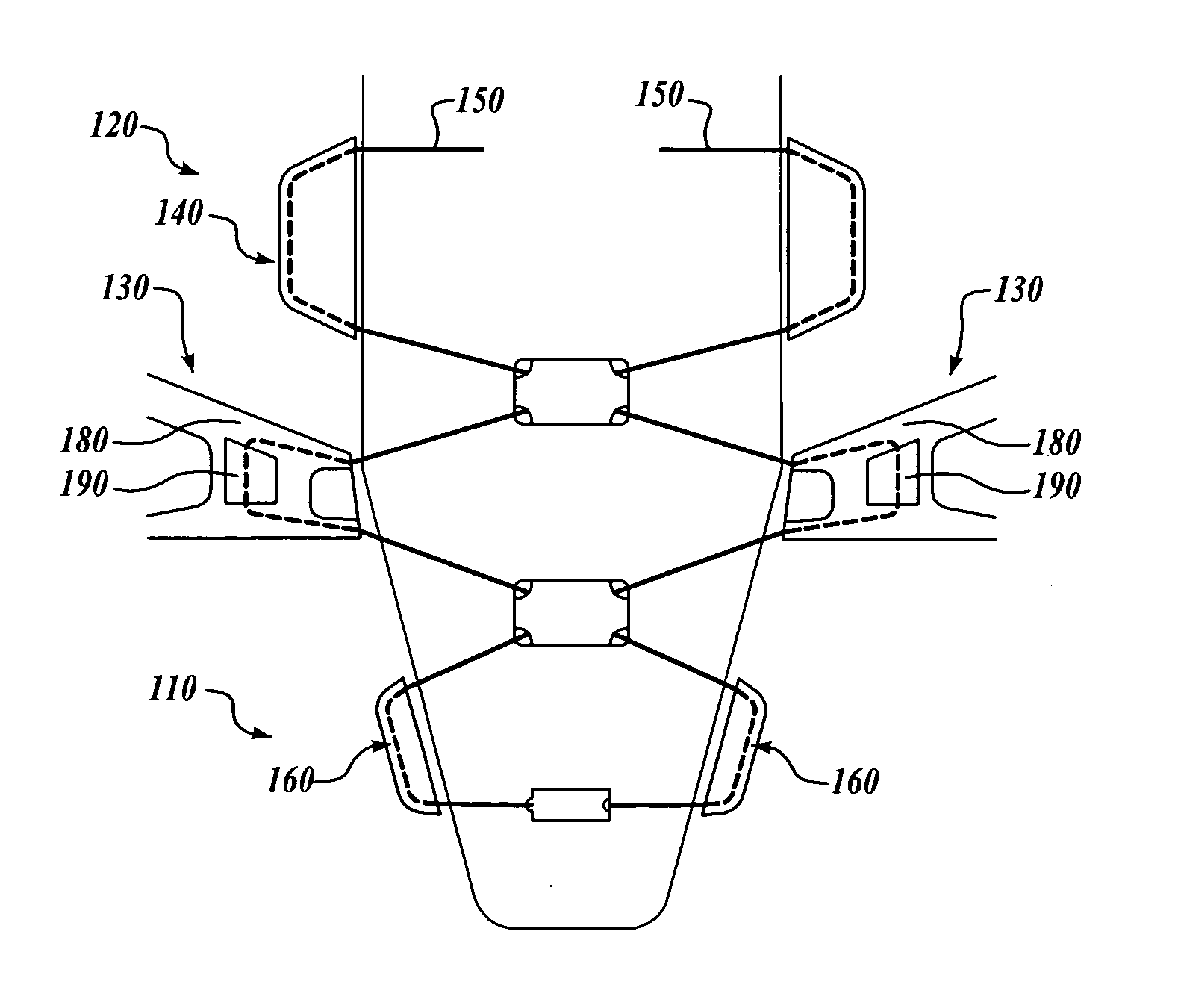
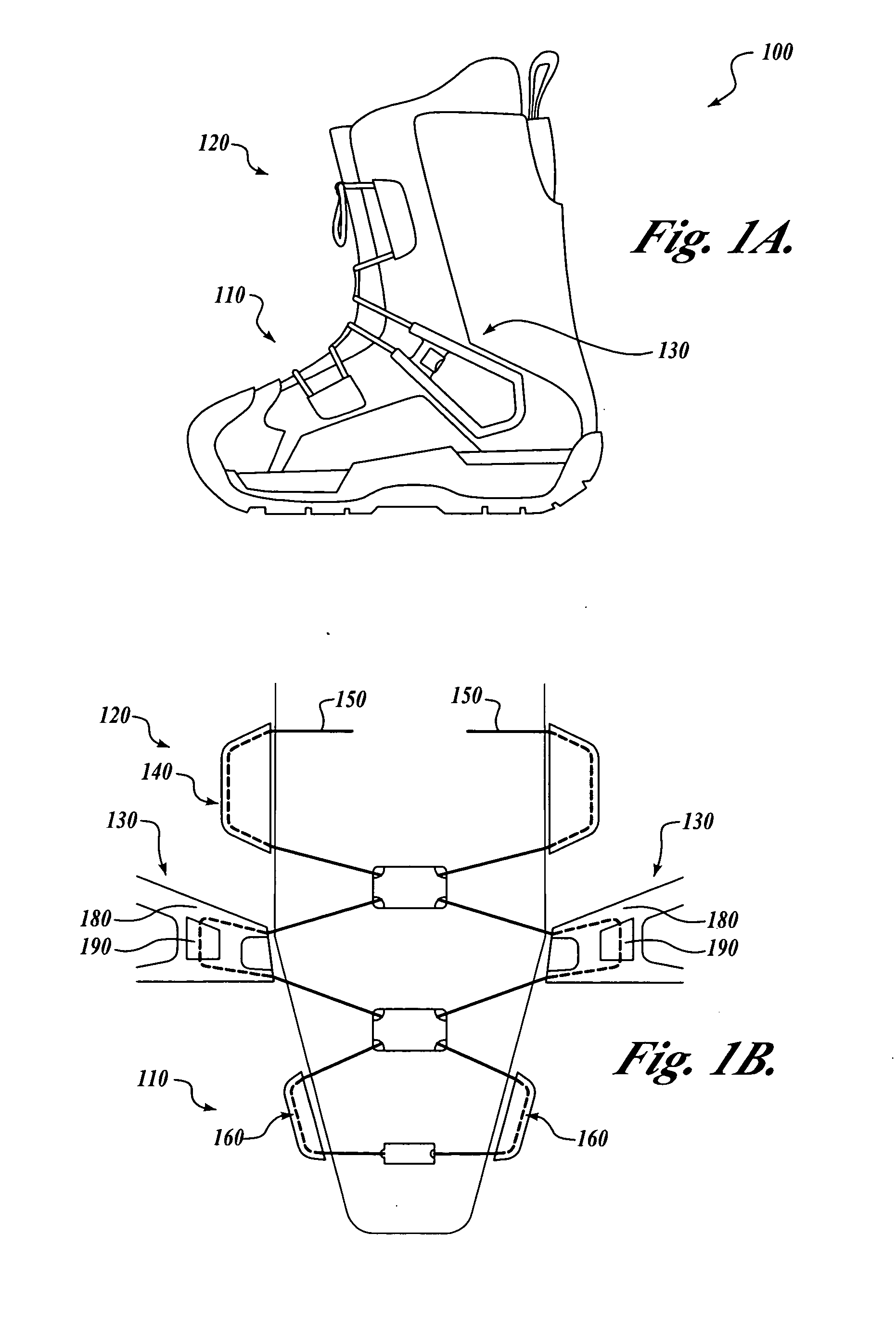
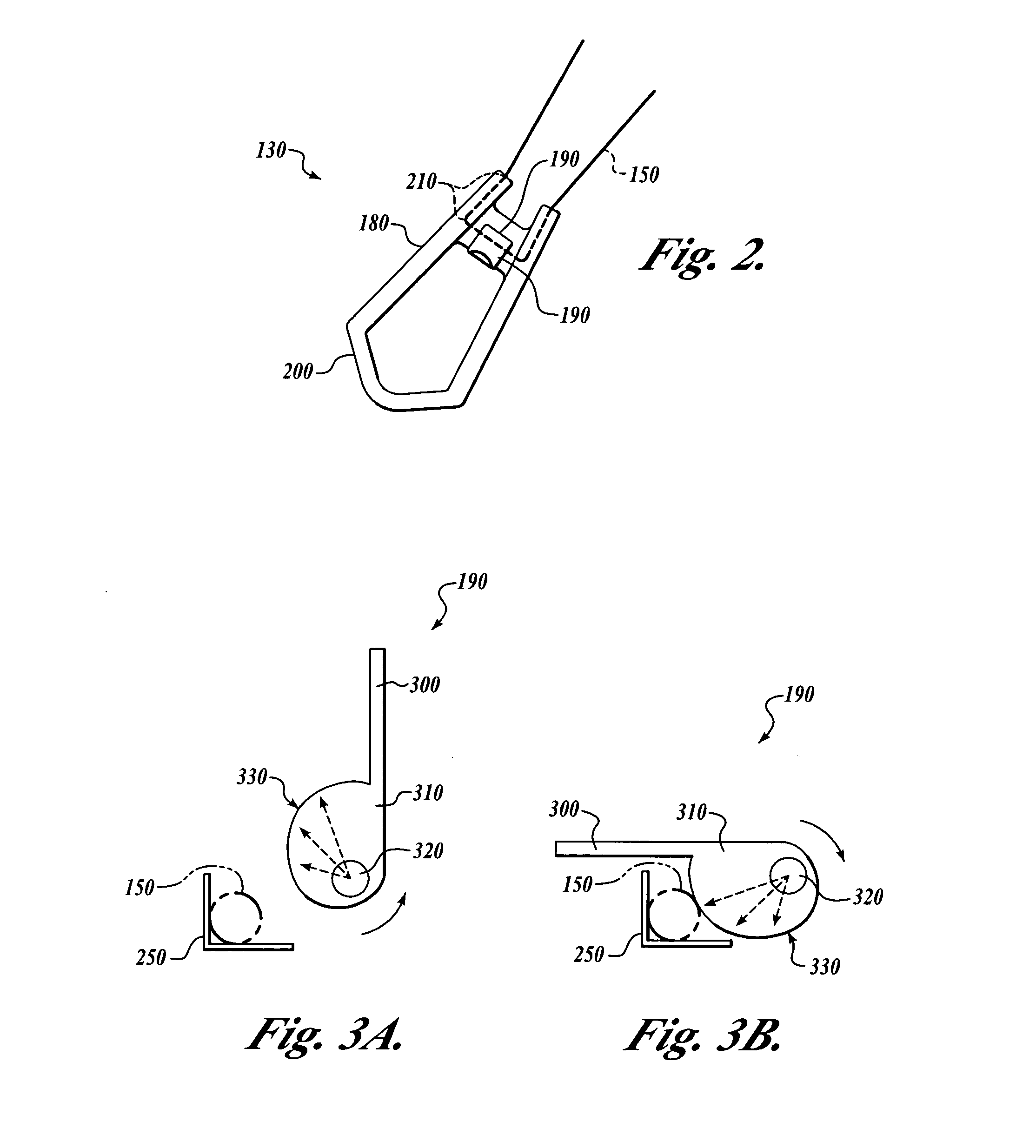
[0007] Embodiments of the present invention provide systems and methods for zonal locking of an article of footwear. Embodiments of the present invention use at least one rotatable locking member to frictionably secure a closure line used to secure the tightness of the closure line between zones of the article of footwear. The rotatable locking member allows tension in the closure line to remain different on opposing sides of the locking member. Also, the rotatable locking member allows the closure line to be locked without kinking or bending the closure line at an acute angle at any point along the line. As a result, the rotatable locking member is particularly advantageous for cable closure lines which practically cannot or should not be bent at acute angles.
[0008] More specifically, embodiments of the present invention provide zonal locking for an article of footwear having a first zone and a second zone. At least one curving point is disposed between a first zone and a second zone of the article of footwear, the curving point being configured so that a closure line curves around the curving point to turn a line of travel of the closure line without bending any single point of the closure line at an acute angle. At least one rotatable closure line lock is configured to move into a locking position wherein the closure line lock frictionably engages the closure line to generally prevent the closure line from moving through the curving point to allow a first tension in the closure line in the first zone to remain different than a second tension in the closure line in the second zone.

Problems solved by technology

Unfortunately, with a conventional lacing system, even if the wearer tightly laces one section of the shoe's upper while leaving another section of the upper less tightly secured, that desired fitting is not likely to last.
Currently used zonal tightening systems, however, are not optimal or suitable for all applications.
Known locking systems, such as Adams's double-loop eyelets are not suitable because it is neither practical nor desirable to bend the cable closure of the boot through the two eyelets to facilitate zonal tightening of the cable.
Similarly, it is neither practical nor desirable to pull and / or bend the cable through a system such as Skaja's elongate locking eyelets which can kink or damage the cable closure.

Method used


Image

  • Footwear closure system with zonal locking
  • Footwear closure system with zonal locking
  • Footwear closure system with zonal locking

Examples


second embodiment

[0032]FIG. 4 is a top view of a closure 400 of a snowboard boot using the present invention. Once again, the closure 400 is a closable opening in an upper of a boot shell, boot liner, or other footwear, such as an opening that secured over a tongue across a top of the wearer's foot or lower extremity. The closure 400 includes a closure line 410 allowing the closure 400 to be closed to secure a boot or other article of footwear (not shown) on the wearer's foot and ankle. The closure line 410 suitably is a lace or a cable. The closure line 410 engages securing points 420 on opposing sides of the closure 400 so that, when tension is applied to the closure line 410, the closure is secured to the user's foot.

[0033] As in the case of the first embodiment of the present invention, a second embodiment of a zonal lock 430 enables the closure line 410 to maintain a first degree of tension in the first zone 440 different from a second degree of tension in the second zone 450. More specifically...

first embodiment

[0037] Also, the rotatable cylinder 500 of the zonal lock 430 is desirably equipped with a gripping ring 540 at a distal end of the rotatable cylinder 500. The gripping ring 540 facilitates a wearer being able to turn the rotatable cylinder 500 when it is in an unlocked position to be able to adjust tension in the closure line 410 in a zone 440 and 450 on either side of the zonal lock 430. As in the case of the invention (FIGS. 1A-3B), one or more additional zones could be added to provide for more than two zones having different degrees of tension in the closure line. An additional zone can be added adjacent to either the first zone 440 (FIG. 4) or the second zone 450 and separated from the adjacent zone by an additional zonal lock 430.

[0038]FIG. 6 is a flowchart of a routine 600 for using a single zonal lock 130 (FIGS. 1B-3B) and 430 (FIGS. 4 and 5) to maintain zonal tightening and locking of two zones of an article of footwear. It will be appreciated that the routine 600 suitably...


PUM


Abstract

Systems and methods for zonal tightening of footwear are disclosed. A zonal locking system for an article of footwear having a first zone and a second zone is provided. At least one curving point is disposed between the first zone and the second zone, the curving point being configured so that a closure line winds around the curving point to turn a line of travel of the closure line without bending any single point of the closure line at an acute angle. At least one rotatable closure line lock is configured to move into a locking position wherein the closure line lock frictionably engages the closure line to generally prevent the closure line from moving through the curving point to allow a first tension in the closure line in the first zone to remain different than a second tension in the closure line in the second zone.

Description

FIELD OF THE INVENTION [0001] This invention relates generally to footwear and, more specifically, to a system and method for adjustably securing the footwear to a wearer's foot. BACKGROUND OF THE INVENTION [0002] Over the last few decades, different ways of closing and securing footwear have been developed. Historically, footwear was designed to slip onto the foot or would be closed with one of laces or a buckling strap. However, with increased popularity of sports, consumers' investment in athletic shoes has resulted in additional techniques for footwear closure and securing systems. For example, athletic shoes were introduced with multiple Velcro® straps for closing the shoes. Also, shoes were introduced with inwardly-directed air bladders which the wearer could adjustably size with a built-in pumping device to custom-fit the shoe. Footwear manufacturers introduced variations on these closure systems and other devices to provide advantages to those selecting their footwear. [0003...

Claims


Application Information

Patent Timeline
Patent Type & Authority Applications(United States)
IPC IPC(8): A43C11/16
CPCA43C11/16A43C1/003A43C11/165
Inventor MARTIN, JOHN DIETRICH
Owner K 2 CORP
Learn More