
Process for preparing polyolefin products

a technology of polyolefin and polyolefin products, which is applied in the field of olefin polymerization and to the preparation of polyolefin products, can solve the problems of troublesome use of alcohols having beta hydrogen atoms in such co-catalyst complexes, ineffective catalysts, and decomposition of alcohol

Inactive Publication Date: 2005-05-12
TPC GROUP
View PDF77 Cites 0 Cited by
  • Summary
  • Abstract
  • Description
  • Claims
  • Application Information

AI Technical Summary

Benefits of technology

[0035] The present invention further provides a novel process for the efficient and economical production of HV-PIB. Generally speaking, the invention provides a HV-PIB production process wherein the polymerization reaction takes place at higher temperatures and at lower reaction times than were thought possible in the past. In particular, the present invention provides a liquid phase polymerization process for preparing low molecular weight, highly reactive polyisobutylene. Generally speaking, the process may involve cationic polymerization. However, under some conditions the polymerization reaction may be covalent. Particularly the latter may be true when ether is used as a complexing agent. In accordance with this embodiment of the invention, the process includes the provision of a feedstock comprising isobutylene and a catalyst composition comprising a complex of BF3 and a complexing agent. The feedstock and the catalyst composition are introduced either separately or as a single mixed stream into a residual reaction mixture in a reaction zone. The residual reaction mixture, the feedstock and the catalyst composition are then intimately intermixed to present an intimately intermixed reaction admixture in said reaction zone. The reaction admixture is maintained in its intimately intermixed condition and kept at a temperature of at least about 0° C. while the same is in said reaction zone, whereby the isobutylene in the reaction admixture is caused to undergo polymerization to form a polyisobutylene product. A product stream comprising a low molecular weight, highly reactive polyisobutylene is then withdrawn from the reaction zone. The introduction of the feedstock into said reaction zone and the withdrawal of the product stream from the reaction zone are controlled such that the residence time of the isobutylene undergoing polymerization in the reaction zone is no greater than about 4 minutes. In accordance with the invention, it is possible to conduct the reaction so that the residence time is no greater than about 3 minutes, no greater than about 2 minutes, no greater than about 1 minute, and ideally, even less than 1 minute.

Problems solved by technology

However, the use of alcohols having beta hydrogen atoms in such co-catalyst complexes is troublesome because, over time, the BF3 tends to attack the beta hydrogen atoms.
This leads to decomposition of the alcohol whereby the catalyst is rendered ineffective.
Thus, the co-catalyst complex is unstable and often has a very short shelf life.

Method used


Image

  • Process for preparing polyolefin products
  • Process for preparing polyolefin products
  • Process for preparing polyolefin products

Examples


example 1

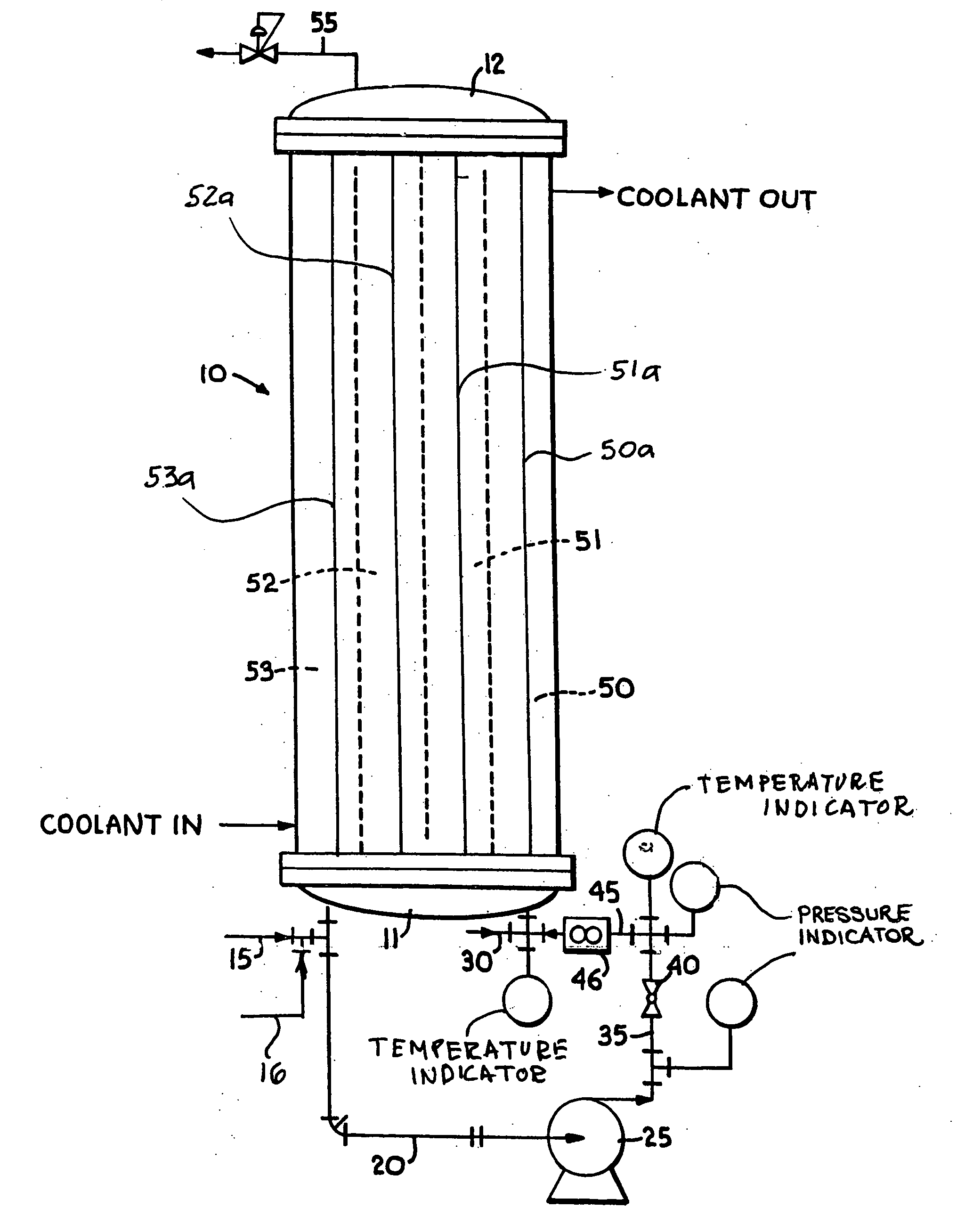
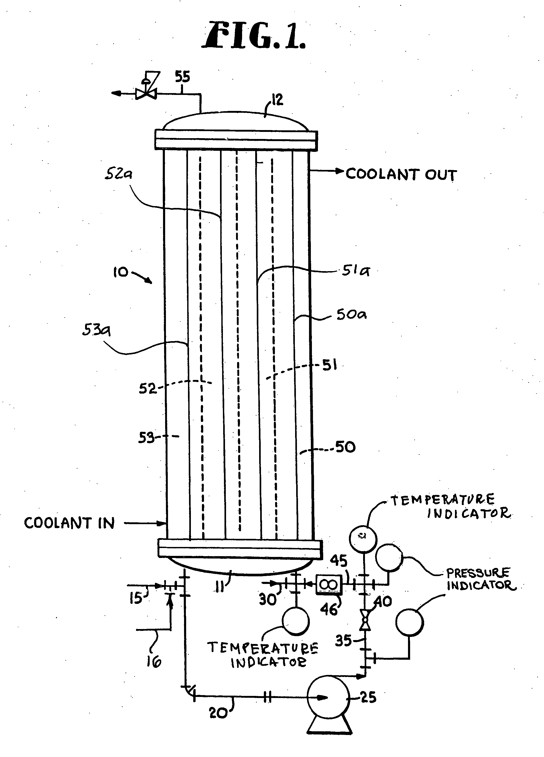
[0074] Using the principles and concepts of the invention, a reactor such as the reactor illustrated in FIG. 1, was used to produce a low molecular weight, highly reactive polyisobutylene. The feedstock was essentially the same as shown above in Table 1, and the coolant circulated on the shell side of the reactor was a mixture of 35 weight % methanol and 65 weight % water. The inlet coolant temperature was 32° F. A 1:1 BF3 / methanol complex catalyst was used. All pertinent reactor data and dimensions are set forth below in Table 4.

TABLE 4Feedstock flow rate1.7gpmRecirculation flow rate50gpmFeedstock density5lb / galConversion63wt %Concentration of isobutylene in92wt %feedstockΔHreaction398Btu / lbμ reaction mixture4.5 cP = 0.0030 lb / ft secCp of reaction mixture0.46Btu / lb ° F.Reaction effective density44.9lb / ft3Thermal conductivity0.075Btu / hr ft ° F.Total volume of reactor recirculation390.2in3Residence time59.6secondsLinear velocity inside tubes9.3ft / secReynolds number3180Surface area ...

example 2

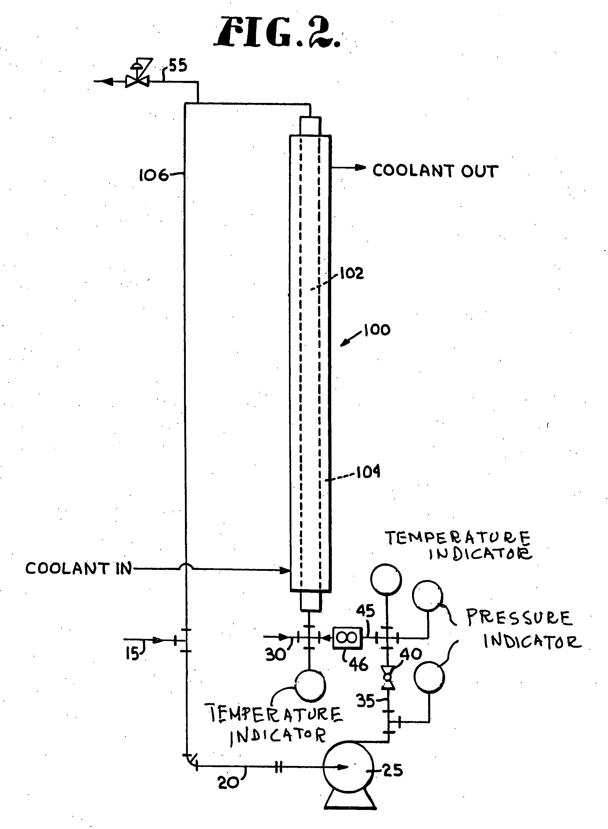
[0080] A stream containing 2.19 wt % Isobutane, 61.5 wt % n-butane, 0.64 wt % 1-butene, 28.18 wt % trans-2-butene and 7.49 wt % cis-2-butene (35.66 wt % 2-butene) is introduced into the a loop reactor system of FIG. 2 via feed line 15 at a rate of 156 ml / min (93.6 g / min). A catalyst complex containing BF3 / methanol complex (one mole of BF3 to one mole of methanol) is fed to the reactor at a rate of 8 mmin (10.4 g / min). The reaction temperature is maintained constant at 90° F. All pertinent reactor data and dimensions are set forth below in Table 6. The reactor effluent exits the top of the reaction loop via line 55 and is fed into a decant (not shown) were the catalyst is preferably separated out from the organic layer. A portion of the catalyst may then be recycled back to the reactor lowering the amount of fresh catalyst required. The product coming out of the decant overhead is mixed with NH4OH to quench any remaining catalyst in the organic phase and is sent to a second decant. T...

example 3

[0082] A stream containing 94.0 wt % 1-decene and 6.0 wt % C10-isomers was fed into the loop reactor of FIG. 2 at a rate of 10 ml / min (7.4 g / min). A catalyst complex containing BF3 / methanol complex (one mole of BF3 to one mole of methanol) was fed to the reactor at a rate of 1 ml / min (1.3 g / min). The reaction was held at a constant temperature of 70° F. All pertinent reactor data and dimensions are given in Table 8. Both the reactor setup and downstream catalyst removal steps are identical to Example 2. The product stream contained about 59.8 wt % of C20 oligomers and about 40.2 wt % of C30 oligomers.

TABLE 8HC flow rate0.00264gpmPump around flow rate1.5gpmHC density6.2lb / gal% Conversion90wt %% 1-decene in feed stock94wt %ΔHrxn318Btu / lbμ1.2 cP = 0.0008 lb / ft sCp0.50Btu / lb° F.Reactor OD0.375inReactor wall thickness0.035inReactor ID0.305inReactor length10.5ftReactor volume9.2in3# of tubes1# of passes1Residence time905.13secondsLinear velocity6.59ft / sSurface area1.03ft2Heat generated4...


PUM

PropertyMeasurementUnit
Reynolds numberaaaaaaaaaa
temperaturesaaaaaaaaaa
temperatureaaaaaaaaaa

Abstract

A novel liquid phase polymerization process for preparing a polyolefin product having preselected properties is disclosed. The process includes the steps of providing a liquid feedstock which contains an olefinic component and a catalyst composition consisting of a stable complex of BF3 and a complexing agent therefor. The feedstock may comprise any one or more of a number of olefins including branched olefins such as isobutylene, C3 to C15 linear alpha olefins and C4 to C15 reactive non-alpha olefins. The feedstock and the catalyst composition are introduced into a residual reaction mixture recirculating in a loop reactor reaction zone provided in the tube side of a shell and tube heat exchanger at a recirculation rate sufficient to cause intimate intermixing of the residual reaction mixture, the added feedstock and the added catalyst composition. The heat of the polymerization reaction is removed from the recirculating intimately intermixed reaction admixture at a rate calculated to provide a substantially constant reaction temperature therein while the same is recirculating in said reaction zone. The conditions in the reactor are appropriate for causing olefinic components introduced in said feedstock to undergo polymerization to form the desired polyolefin product in the presence of the catalyst composition. A product stream containing the desired polyolefin product is withdrawn from the reaction zone. The introduction of the feedstock into the reaction zone and the withdrawal of the product stream from the reaction zone are controlled such that the residence time of the olefinic components undergoing polymerization in the reaction zone is appropriate for production of the desired polyolefin product.

Description

CROSS REFERENCE TO RELATED APPLICATIONS [0001] This application is a continuation of copending utility application Ser. No. 10 / 208,234 filed Jul. 30, 2002, which in turn is a continuation of utility application Ser. No. 09 / 655,084 filed on Sep. 20, 2000, which again in turn is a continuation-in-part of utility application Ser. No. 09 / 515,790 filed on Feb. 29, 2000. Priority from each of said copending utility applications is claimed herein pursuant to 35 U.S.C. § 120. In addition, priority benefits under 35 U.S.C. §119(e) are claimed in this application from provisional application Ser. No. 60 / 160,357, filed on Oct. 19, 1999. The entireties of the disclosures of said prior applications are hereby specifically incorporated herein by reference.BACKGROUND OF THE INVENTION [0002] 1. Field of the Invention [0003] The present invention relates to olefin polymerization and to the preparation of polyolefin products. In particular the present invention relates to the preparation of a variety...

Claims


Application Information

Patent Timeline
Patent Type & Authority Applications(United States)
IPC IPC(8): C08F2/00C08F10/00C08F10/10C08F110/10C08F110/14C08F210/10
CPCC08F10/00C08F10/10C08F110/10C08F110/14C08F210/10C08F4/14C08F2500/20C08F2500/02C08F210/08
Inventor BAXTER, C. EDWARD JR.VALDEZ, GILBERTLOBUE, CHRISTOPHERLOWRY, TIMOTHYABAZAJIAN, ARMEN
Owner TPC GROUP
Learn More