
Method and apparatus for mapping TDM payload data

a payload data and method technology, applied in the direction of electrical equipment, radio transmission, transmission, etc., can solve the problems of limiting the number of signals, lack of reliable failover mechanisms, and art methodologies

Inactive Publication Date: 2005-05-12
EMERSON NETWORK POWER EMBEDDED COMPUTING
View PDF4 Cites 41 Cited by
  • Summary
  • Abstract
  • Description
  • Claims
  • Application Information

AI Technical Summary

Problems solved by technology

These prior art methodologies have the disadvantage of limiting the number of signals that can be channeled through each payload node in the chassis.
Another disadvantage is the lack of provisions for reliable failover mechanisms if a payload node fails.

Method used


Image

  • Method and apparatus for mapping TDM payload data
  • Method and apparatus for mapping TDM payload data
  • Method and apparatus for mapping TDM payload data

Examples


Embodiment Construction

[0008] In the following detailed description of exemplary embodiments of the invention, reference is made to the accompanying drawings, which illustrate specific exemplary embodiments in which the invention may be practiced. These embodiments are described in sufficient detail to enable those skilled in the art to practice the invention, but other embodiments may be utilized and logical, mechanical, electrical and other changes may be made without departing from the scope of the present invention. The following detailed description is, therefore, not to be taken in a limiting sense, and the scope of the present invention is defined only by the appended claims.

[0009] In the following description, numerous specific details are set forth to provide a thorough understanding of the invention. However, it is understood that the invention may be practiced without these specific details. In other instances, well-known circuits, structures, software blocks and techniques have not been shown...


PUM


Abstract

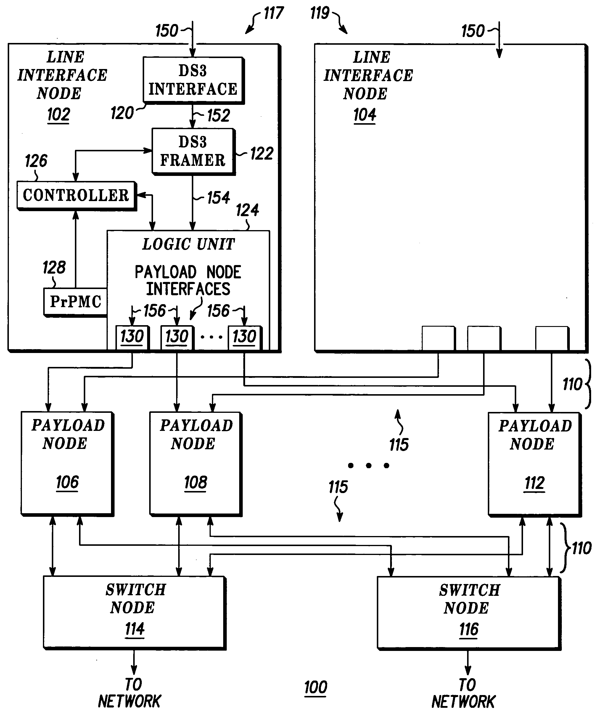
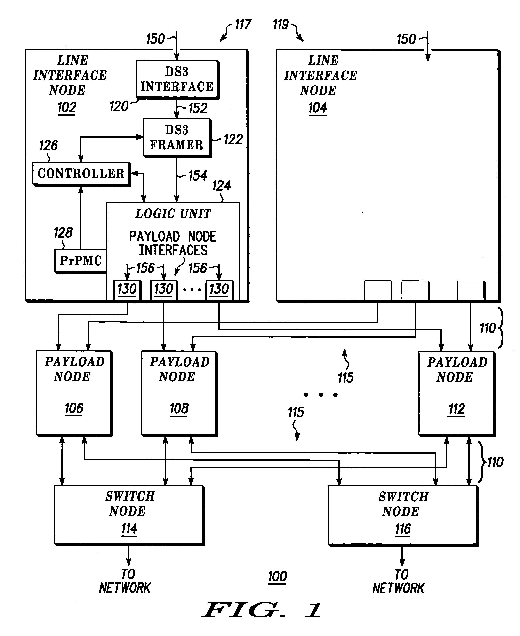
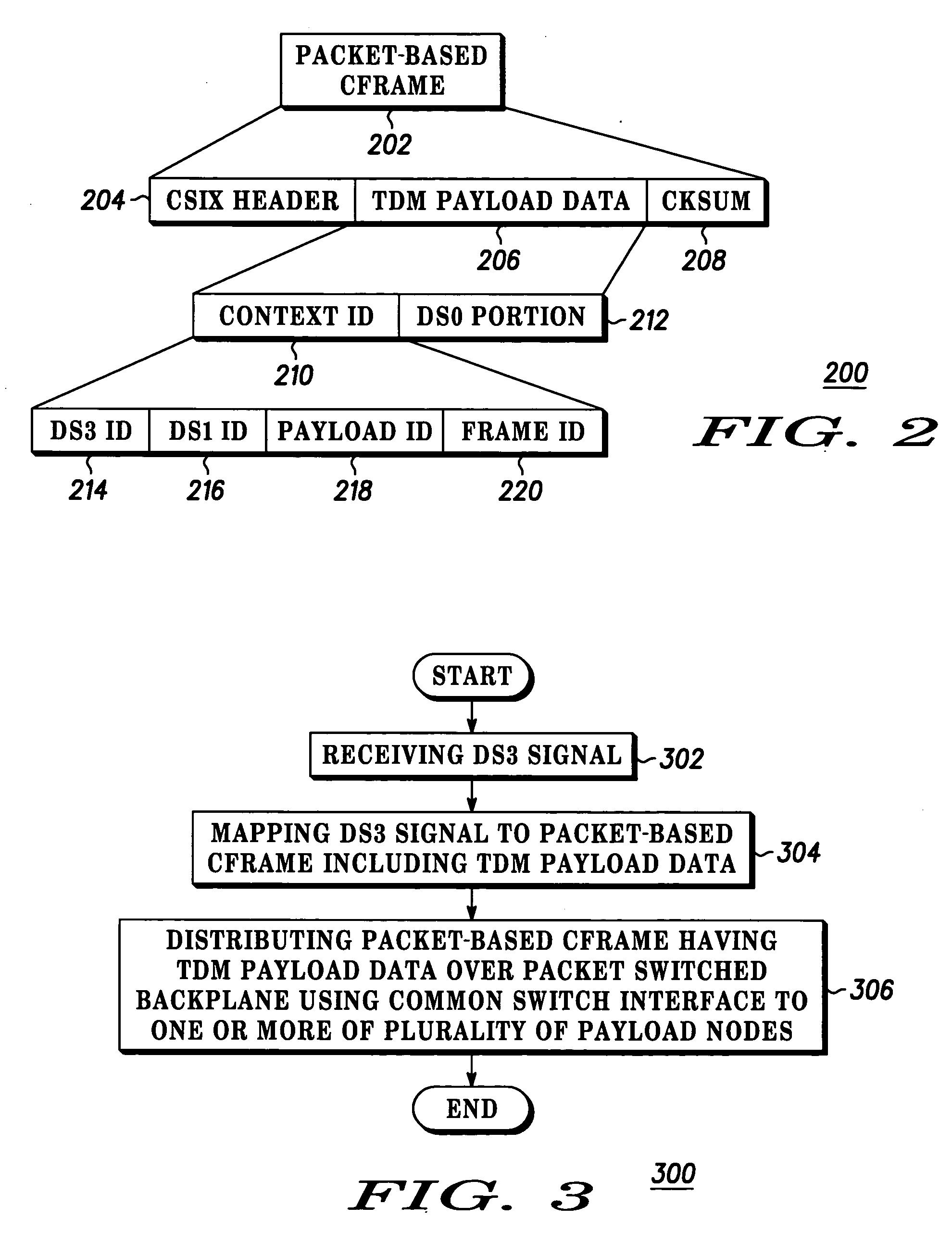
A method and apparatus includes a DS3 framer (122) receiving a DS3 signal (150) having TDM payload data (152) at a line interface node (102, 104). A logic unit (124) at the line interface node maps the DS3 signal to a packet-based Cframe (156) at the line interface node, wherein the packet-based Cframe includes the TDM payload data (152). The packet-based Cframe having the TDM payload data is distributed over a packet switched backplane (110) using a Common Switch Interface (115) to one or more of a plurality of payload nodes (106, 108, 112).

Description

BACKGROUND OF THE INVENTION [0001] Prior art methods of receiving time division multiplexed (TDM) signals into a chassis-type network includes channeling DS3 signals to each individual payload node or using dedicated path (as provided in H.110) to distribute DS3 signals to payload nodes within a chassis. These prior art methodologies have the disadvantage of limiting the number of signals that can be channeled through each payload node in the chassis. Another disadvantage is the lack of provisions for reliable failover mechanisms if a payload node fails. [0002] Accordingly, there is a significant need for an apparatus and method that overcomes the disadvantages of the prior art outlined above.BRIEF DESCRIPTION OF THE DRAWINGS [0003] Referring to the drawing: [0004]FIG. 1 depicts a block diagram of a multi-service platform system according to one embodiment of the invention; [0005]FIG. 2 illustrates a packet-based Cframe in accordance with an embodiment of the invention; and [0006]FI...

Claims


Application Information

Patent Timeline
Patent Type & Authority Applications(United States)
IPC IPC(8): H04B7/212H04B7/26
CPCH04B7/2643
Inventor HALLIDAY, DAVID J.
Owner EMERSON NETWORK POWER EMBEDDED COMPUTING
Learn More