Eureka AIR delivers breakthrough ideas for toughest innovation challenges, trusted by R&D personnel around the world.

Telescope main body and spotting scope

a telescopic and spotting scope technology, applied in the field of telescopic main body and spotting scope, can solve the problems of troublesome diopter adjustment, inconvenient use of fieldscope, and inability to accurately focus images captured by imaging devices

Inactive Publication Date: 2005-05-12
RICOH IMAGING COMPANY
View PDF5 Cites 14 Cited by
  • Summary
  • Abstract
  • Description
  • Claims
  • Application Information

AI Technical Summary

Benefits of technology

"The present invention provides a telescope and spotting scope with a correcting system that can reliably correct focal shift caused by diopter variation of the user. The correcting system includes a focus driving system, a focus detecting system, and a controller that controls the focus driving system. The telescope and spotting scope can be calibrated at start of use or at regular intervals to ensure accurate and reliable image capture. The learning function of the controller takes into account the previous correcting operations and uses the stored correction data to correct the position shift between the visual image and the object image. The calibration point can be updated based on the driving direction and amount of the focus driving system. The correction data includes the driving direction and amount of the focus driving system. The telescope and spotting scope can be used with an ocular optical system and the focus adjusting member can be manipulated for focusing. The learning function is performed by storing the correction data of a plurality of preceding correcting operations and using the stored correction data for each user."

Problems solved by technology

In other words, though the image viewed through the eyepiece appears correctly focused, the image captured by the imaging device may not be correctly focused.
However, the fieldscope with a DV camera according to the document 1 still has a drawback that the manipulation of the diopter adjustment is troublesome, and the fieldscope is therefore not user-friendly.
Besides, since the visual image viewed through the eyepiece can any way be focused upon manipulating a focusing ring regardless of whether the diopter adjustment is performed or not, the troublesome diopter adjustment operation is prone to be skipped or forgotten, which may result in producing a blurred picture with a focal shift.
Further, even though the diopter adjustment has been performed, the adjustment may still be unsharp (inaccurate) depending on focusing capability of the user's eye.
Furthermore, even though the diopter adjustment has been correctly performed at first, the user's diopter may vary with time owing to eye strain, instrument myopia or a change of a condition of use, therefore subsequent shots may result in blurred pictures.

Method used


Image

  • Telescope main body and spotting scope
  • Telescope main body and spotting scope
  • Telescope main body and spotting scope

Examples


Embodiment Construction

[0042] Referring to the accompanying drawings, preferable embodiments of a telescope main body and a spotting scope according to the present invention will be described hereunder.

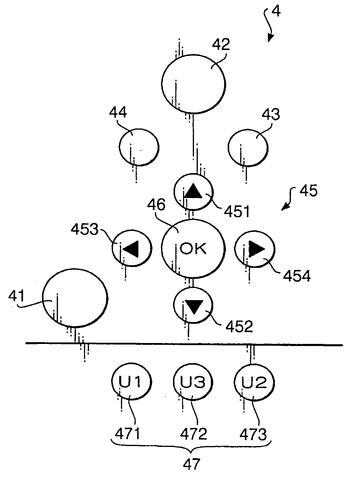
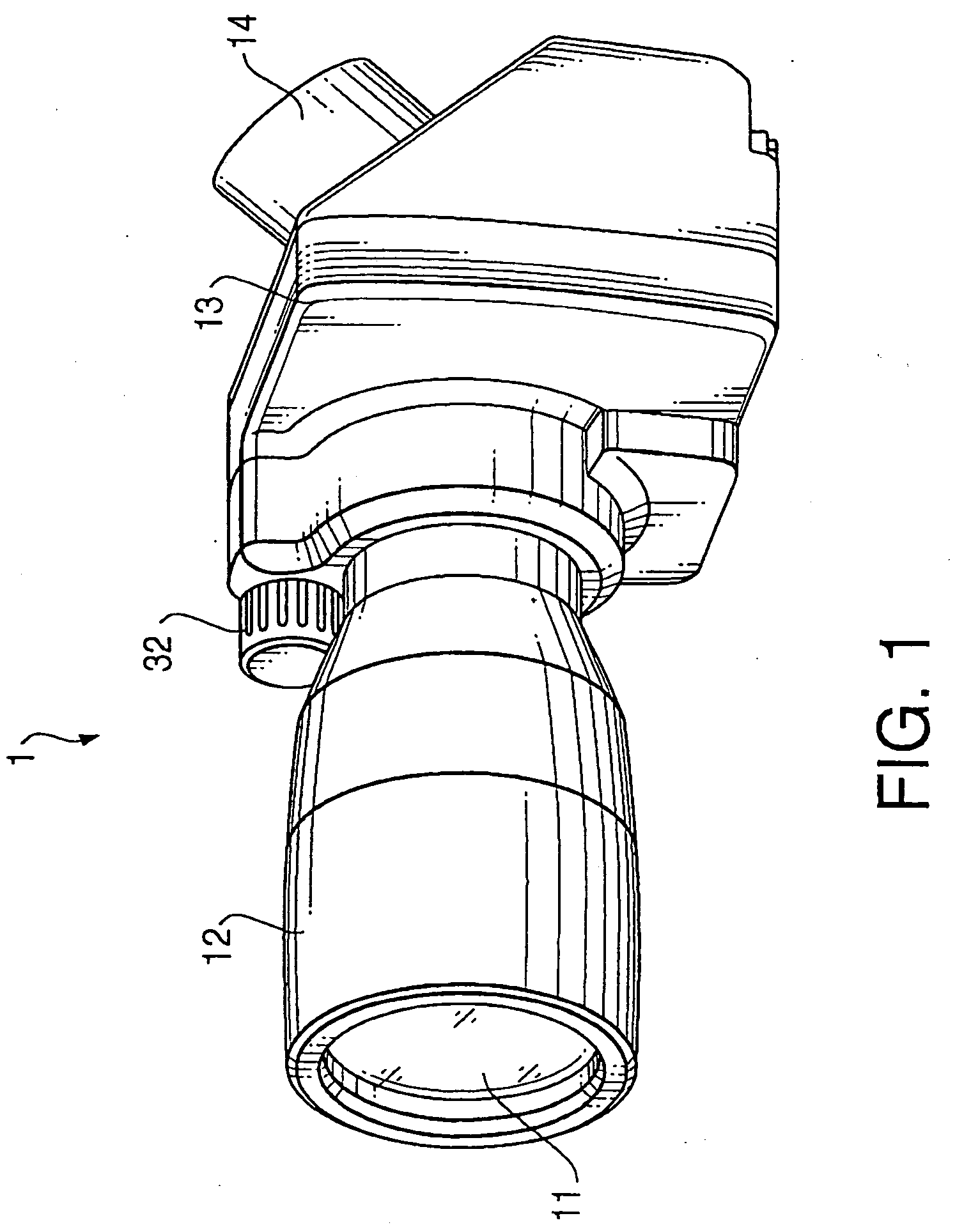
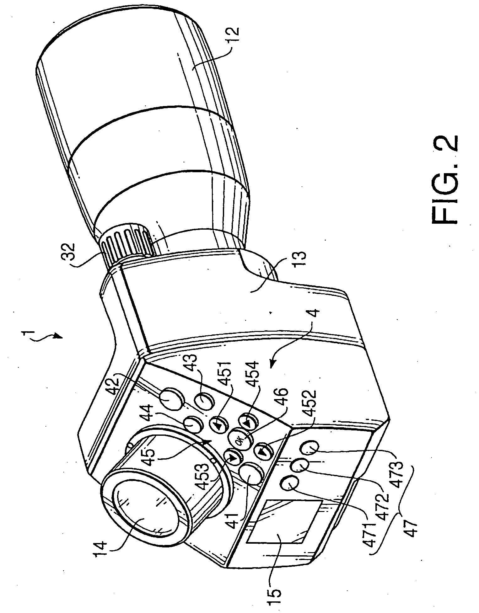
[0043]FIG. 1 is a perspective front view showing a telescope main body according to an embodiment of the present invention; FIG. 2 is a perspective rear view showing the telescope main body of FIG. 1; FIG. 3 illustrates a layout of operating buttons of the telescope main body of FIG. 1; FIG. 4 is a cross-sectional side view showing the telescope main body of FIG. 1; FIG. 5 is a perspective exploded view showing an optical system of the spotting scope according to the present invention; FIG. 6 is a side view showing a prism unit viewed from an opposite side of FIG. 4; and FIG. 7 is a block diagram showing a configuration of the telescope main body of FIG. 1.

[0044] The telescope main body 1 according to the embodiment shown in these drawings is to be combined with an eyepiece 2, to thereby constitute a spot...


PUM


Abstract

A telescope main body, which is provided with an objective optical system, a focusing system, an imaging device, a beam splitter, and a correcting system that performs a correcting operation for correcting a position shift between an image forming position of an object image and a receiving surface of the imaging device caused by diopter variation of a user. The correcting system includes a focus driving system which relatively moves an image forming position of the object image with respect to the receiving surface, a focus detecting system which detects a status in which the image forming position coincides with the receiving surface, and a controller controlling the focus driving system. The controller has with a learning function of storing correction data of a preceding correcting operation so that the stored correction data of the preceding correcting operation is reflected in a subsequent correction operation.

Description

BACKGROUND OF THE INVENTION [0001] The present invention relates to a telescope main body and a spotting scope. [0002] A telescope (spotting scope) with a digital camera is known, which is capable of shooting an electronic image that is the same as a visual image viewed through an eyepiece thereof. Such a telescope is disclosed, for example, in a Japanese Utility Model Publication No. 3074642 (hereafter, referred to as a document 1). The telescope with a digital camera is provided with a beam splitter for splitting a light beam that has passed through an objective optical system and a focusing lens, and leading one of the resultant split beams to an ocular optical system and the other to an imaging device such as a CCD (charge coupled device) imaging device. [0003] Such telescope with digital camera may incur a focal shift between a visual image viewed through the eyepiece and an object image captured by the imaging device, because of diopter variation of a user, such as hyperopia o...

Claims


Application Information

Patent Timeline
Patent Type & Authority Applications(United States)
IPC IPC(8): G02B7/08G02B23/06G02B7/28G02B7/36G02B17/04G02B23/00G02B23/12H04N5/225H04N5/232
CPCG02B7/08G02B17/04G02B23/12H04N23/55H04N23/673H04N23/631
Inventor MOGAMIYA, MAKOTOMASUDA, TOSHIO
Owner RICOH IMAGING COMPANY
Why Eureka
Eureka Blog
Learn More