
Parallel imaging compatible birdcage resonator

a resonator and parallel imaging technology, applied in the field of local coils, can solve the problems of limited imaging speed, single coil approach, and limited ultimate speed of most sequential imaging techniques, and achieve the effect of improving the signal-to-noise ratio of the bird cage coil

Inactive Publication Date: 2005-05-12
BAYER HEALTHCARE LLC
View PDF11 Cites 31 Cited by
  • Summary
  • Abstract
  • Description
  • Claims
  • Application Information

AI Technical Summary

Benefits of technology

The invention provides a birdcage coil for use with an MR system that can acquire images of a region of interest using parallel imaging techniques. The coil has a first and second rings and a plurality of rods that connect them. The rods form partially-overlapped primary resonant substructures that provide a homogeneous pattern of magnetic flux density in at least one of three orthogonal imaging planes of the coil while maintaining or improving the signal-to-noise ratio. The substructures can be used simultaneously by the MR system for reception of magnetic resonance signals from the region of interest. The technical effect of the invention is to improve the image quality and accuracy of MRIs using the birdcage coil.

Problems solved by technology

The disadvantage of the single coil approach is attributable to just one coil structure being used to acquire the MR signals over the entire region of interest.
Thus, imaging speed is generally limited by the maximum switching rates compatible with scanner technology and patient safety.
Whereas the ultimate speeds of most sequential imaging techniques are limited by physical and physiologic constraints on gradient switching rate and RF power deposition, achievable SMASH imaging speeds are limited in principle only by the number and arrangement of RF array elements which may reasonably be constructed and interfaced with an MR scanner.
The prior art head coils disclosed in the above-cited patents were not originally built for operation with MR systems capable of acquiring images of the head using parallel imaging techniques.
Because of that overlap, the head coil is not appropriate for acquiring images using parallel imaging techniques.

Method used


Image

  • Parallel imaging compatible birdcage resonator
  • Parallel imaging compatible birdcage resonator
  • Parallel imaging compatible birdcage resonator

Examples


Embodiment Construction

[0052] The presently preferred and alternative embodiments and related aspects of the invention will now be described with reference to the accompanying drawings, in which like elements have been designated where possible by the same reference numerals.

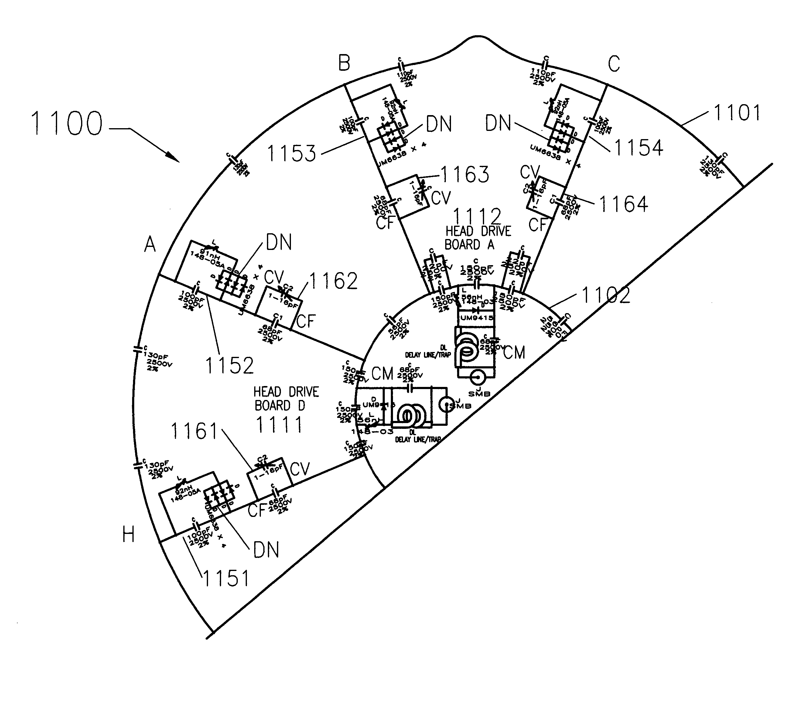
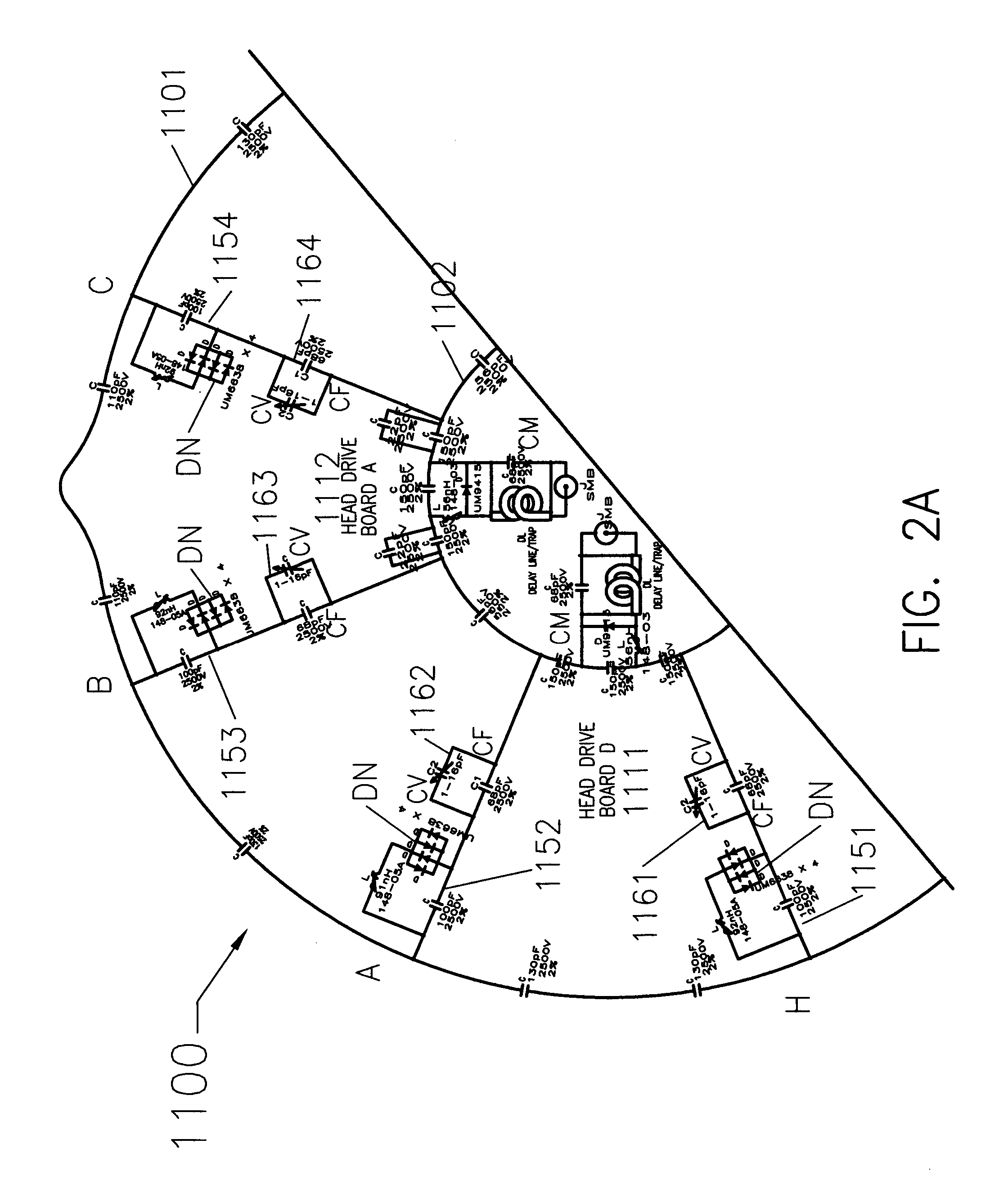
[0053]FIG. 2 is a schematic diagram for a presently preferred embodiment of a tapered birdcage resonator, or Head Coil section 1000, for a Neurovascular Array (NVA), showing the circuit components and their respective values. The head coil 1000 shown in FIG. 2 is a “receive only” resonator, i.e., it does not apply the RF excitation pulses. It may, however, be configured to operate as a transmit / receive (T / R) coil. When configured as a receive only resonator, the head coil 1000 shall be used with an external transmit coil, such as the RF body coil of the host MR system.

[0054] The tapered birdcage resonator 1000 comprises two electrically conductive end rings 1101 and 1102, one smaller than the other, interconnected by a plurality of ...


PUM


Abstract

A birdcage coil for use with a magnetic resonance (MR) system comprises a first ring at one thereof, a second ring at the other end thereof, and a plurality of rods electrically interconnecting the first and second rings. The first ring is electrically conductive and has a first diameter. The second ring is electrically conductive and has a second diameter. The rods and first and second rings are configured to form about the birdcage coil a plurality of partially-overlapped primary resonant substructures. Each primary resonant substructure includes two of the rods and the corresponding sections of the first and second rings interconnecting them.

Description

CROSS-REFERENCE TO RELATED APPLICATION(S) [0001] This application for patent claims the benefit of U.S. Provisional Application Ser. No. 60 / 429,855 titled Parallel Imaging Compatible Birdcage Resonator, filed Nov. 27, 2002. This provisional application has been assigned to the assignee of the invention disclosed below, and its teachings are incorporated into this document by reference.FIELD OF THE INVENTION [0002] The invention generally relates to the field of magnetic resonance (MR) imaging and spectroscopy systems and to the various types of local coils used with such systems. More particularly, the invention pertains to local coils, such as those used to image the human head, which are designed to be used with 8-channel MR systems capable of acquiring images using parallel imaging techniques. BRIEF DESCRIPTION OF RELATED ART [0003] The following information is provided to assist the reader to understand the environment in which the invention disclosed herein will typically be us...

Claims


Application Information

Patent Timeline
Patent Type & Authority Applications(United States)
IPC IPC(8): G01R33/34
CPCG01R33/34046
Inventor MONSKI, WILLIAM J. JR.ALRADADY, FAHADMISIC, GEORGE J.
Owner BAYER HEALTHCARE LLC
Learn More