
Method for visual-based recognition of an object

a visual-based and object-based technology, applied in the field of object recognition, can solve the problems of many difficult problems, methods have great difficulty in separating objects from the scene background, and many object poses are more difficult to distinguish from each other

Inactive Publication Date: 2005-05-05
HEWLETT PACKARD DEV CO LP
View PDF19 Cites 135 Cited by
  • Summary
  • Abstract
  • Description
  • Claims
  • Application Information

AI Technical Summary

Benefits of technology

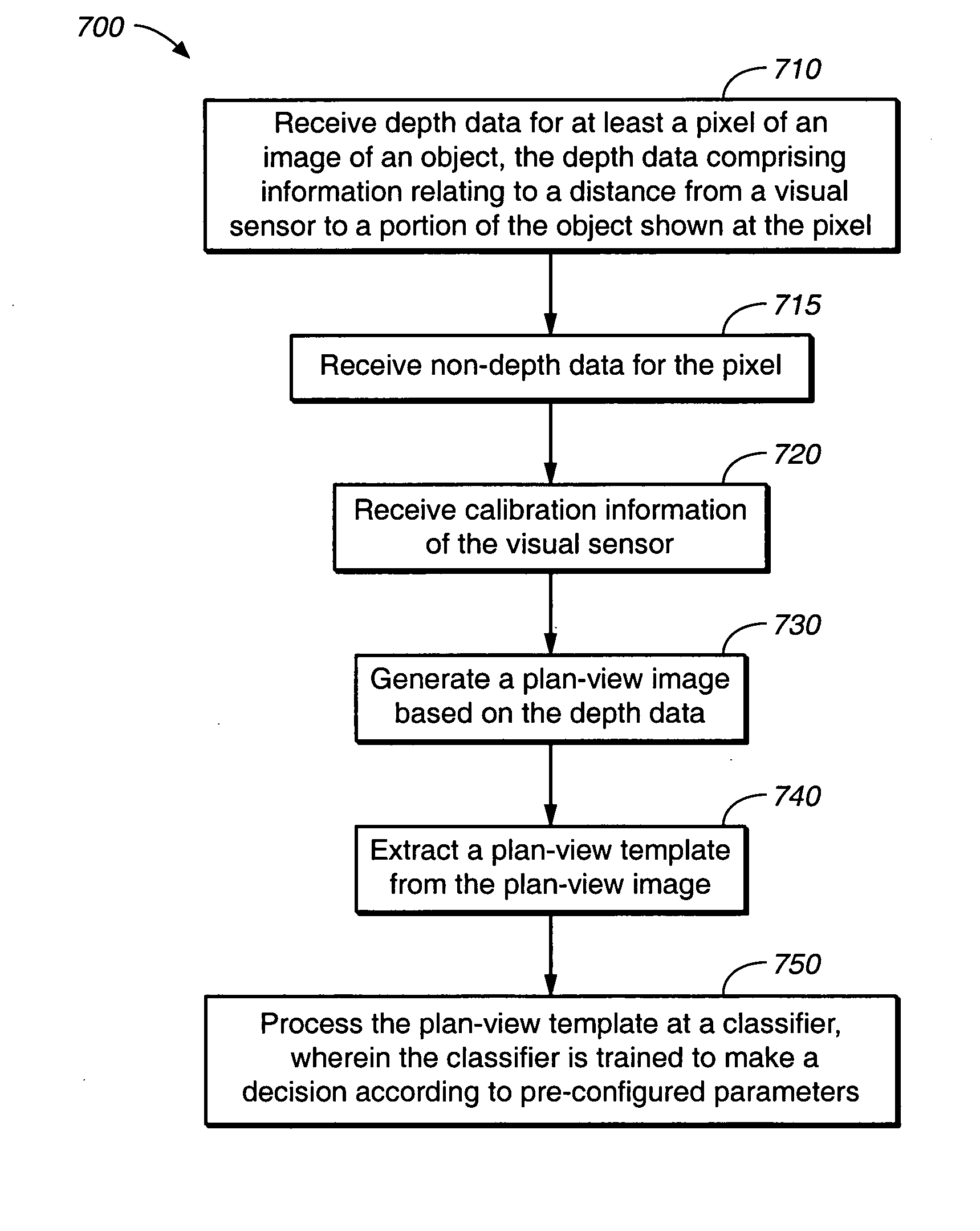
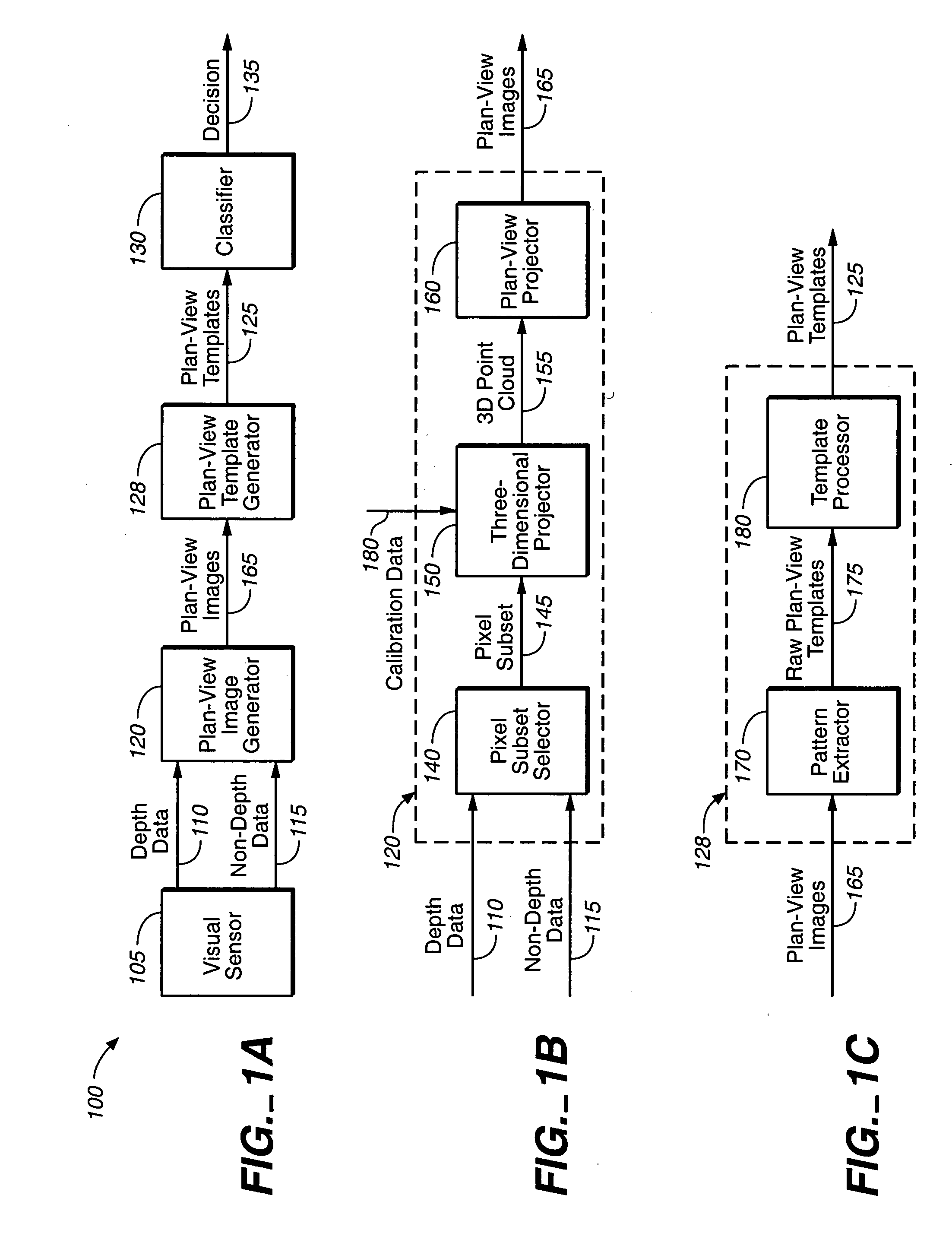
The present invention describes a method for recognizing objects using depth data from images. The method involves receiving the depth data for at least one pixel of an image of an object and generating a plan-view image based on the depth data. A template is then extracted from the plan-view image and processed at a classifier, which is trained to make a decision based on preconfigured parameters. The technical effect of this invention is to provide a more accurate and efficient method for recognizing objects using depth data from images.

Problems solved by technology

Currently, vision-based person and object perception is beset by many difficult challenges, including segmentation of people from the background, discrimination of people from other foreground objects, tracking of people through occlusions and close interactions, and modeling of the highly articulated human form.
As a result, these methods have great difficulty in separating objects from the scene background, in gauging the true physical size of the objects, and in determining accurate three-dimensional (3D) shape and orientation information about the objects.
By attempting to implicitly obtain depth data, many object poses are more difficult to distinguish from each other in some camera views, and it is typically more difficult to construct recognition algorithms that are invariant to the location of the camera relative to the observed objects.
Also, these methods tend to be highly error prone.
Such processes, particularly in the case of articulated, human bodies, are typically quite complex and noise sensitive, and therefore must employ extensive, often iterative calculations to avoid being highly error-prone.
As a result, these methods are highly computational, requiring extensive computational resources, and are time consuming.
However, due to the limitations of current automated monitoring methods, accuracy and / or prompt response time may not be provided, reducing the effectiveness and safety provided by current automated monitoring methods.

Method used


Image

  • Method for visual-based recognition of an object
  • Method for visual-based recognition of an object
  • Method for visual-based recognition of an object

Examples


Embodiment Construction

[0022] Reference will now be made in detail to various embodiments of the invention, examples of which are illustrated in the accompanying drawings. While the invention will be described in conjunction with these embodiments, it will be understood that they are not intended to limit the invention to these embodiments. On the contrary, the invention is intended to cover alternatives, modifications and equivalents, which may be included within the spirit and scope of the invention as defined by the appended claims. Furthermore, in the following description of the present invention, numerous specific details are set forth in order to provide a thorough understanding of the present invention. In other instances, well-known methods, procedures, components, and circuits have not been described in detail as not to unnecessarily obscure aspects of the present invention.

[0023] Aspects of the present invention may be implemented in a computer system that includes, in general, a processor for...


PUM


Abstract

A method for visual-based recognition of objects is described. Depth data for at least a pixel of an image of the object is received, the depth data comprising information relating to a distance from visual sensor to a portion of the object visible at the pixel. At least one plan-view image is generated based on the depth data. At least one plan-view template is extracted from the plan-view image. The plan-view template is processed by at least one classifier, wherein the classifiers are trained to make a decision according to pre-configured parameters.

Description

TECHNICAL FIELD [0001] Embodiments of the present invention relate to the field of object recognition. Specifically, embodiments of the present invention relate to a method and system for visual-based recognition of the type, identity, or configuration of an object. BACKGROUND ART [0002] The automated monitoring of the presence, location, and activities of people is a fundamental technology that enables many new, context-aware applications in domains ranging from “intelligent environments” to security and surveillance. Achievement of this via video cameras has the great appeal of not requiring any special behavior, awareness, or instrumentation of those being observed, while the cameras employed may be shared with other applications, such as teleconferencing, and may provide human observers with the means to record and verify the automated analysis. Currently, vision-based person and object perception is beset by many difficult challenges, including segmentation of people from the b...

Claims


Application Information

Patent Timeline
Patent Type & Authority Applications(United States)
IPC IPC(8): G06K9/00G06K9/46G06K9/62
CPCG06K9/00201G06K9/4647G06K9/00369G06K9/00228G06V20/64G06V40/161G06V40/103G06V10/507
Inventor HARVILLE, MICHAEL
Owner HEWLETT PACKARD DEV CO LP
Learn More