
Position sensing electronic torque wrench

a technology of electronic torque wrench and torque sensor, which is applied in the direction of wrenches, screwdrivers, manufacturing tools, etc., can solve the problems of low torque condition that may not provide enough friction to keep the fastener in place, immediate or eventual failure of the fastener, and serious safety problems, etc., to achieve high torque and high torque

Inactive Publication Date: 2005-05-05
LEHNERT MARK W +2
View PDF17 Cites 58 Cited by
  • Summary
  • Abstract
  • Description
  • Claims
  • Application Information

AI Technical Summary

Benefits of technology

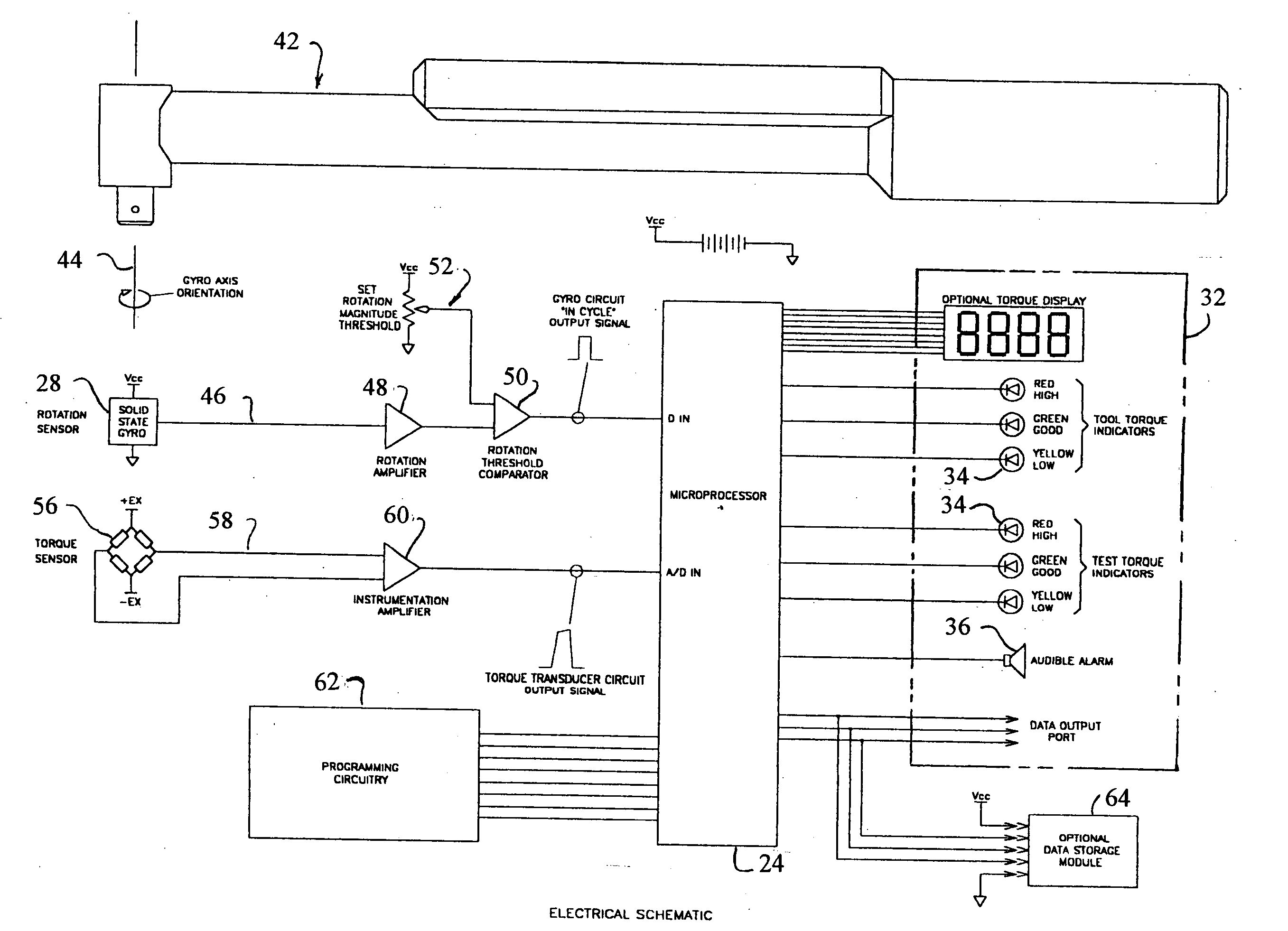
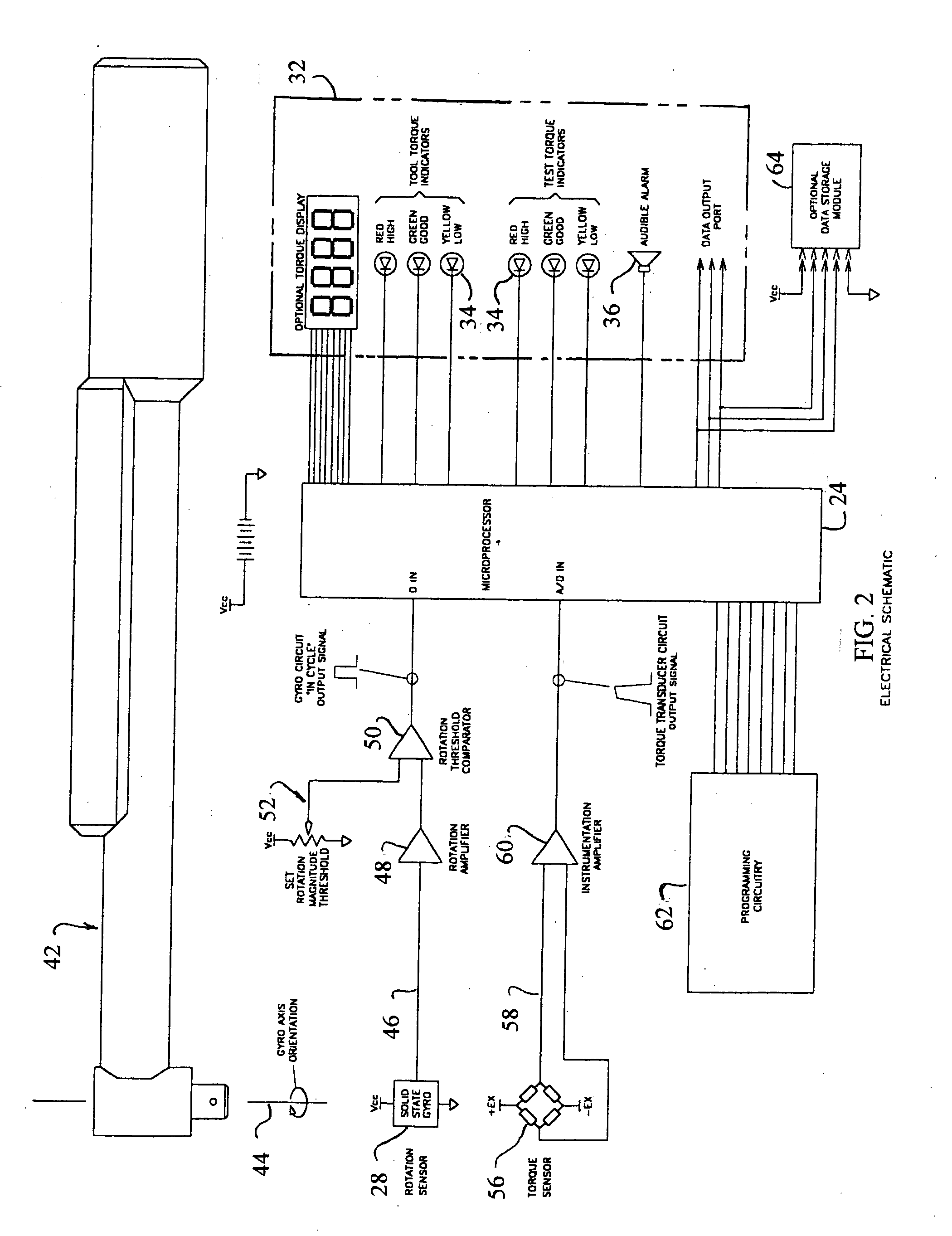
[0003] Therefore, the present invention provides means for sensing fastener rotation during torque verification processes. The present invention can incorporate a solid state, single axis gyro circuit into a torque-testing wrench that can include at least one strain gauge, an instrumentation amplifier and a data collection microprocessor. Programming the “High” and “Low” limits are accomplished by data entry at the control panel on the tool. With a rotation signal available, data collection can be timed with actual movement of the fastener. The collected data can be compared against high and low torque limits two times during each test. The first compare can be executed as the fastener begins rotation. This torque value can be the actual break-away torque required to exceed the force applied b

Problems solved by technology

A low torque condition may not provide enough friction to keep the fastener in place.
Application of too much torque can cause an immediate or eventual failure of the fastener.
In either case serious safety issues may exist.
Although these systems may be very accurately calibrated, use of these tools is a subjective process.
The concern with this type of minimum torque test is that a dangerously high final torque will not be detected.

Method used


Image

  • Position sensing electronic torque wrench
  • Position sensing electronic torque wrench
  • Position sensing electronic torque wrench

Examples


Embodiment Construction

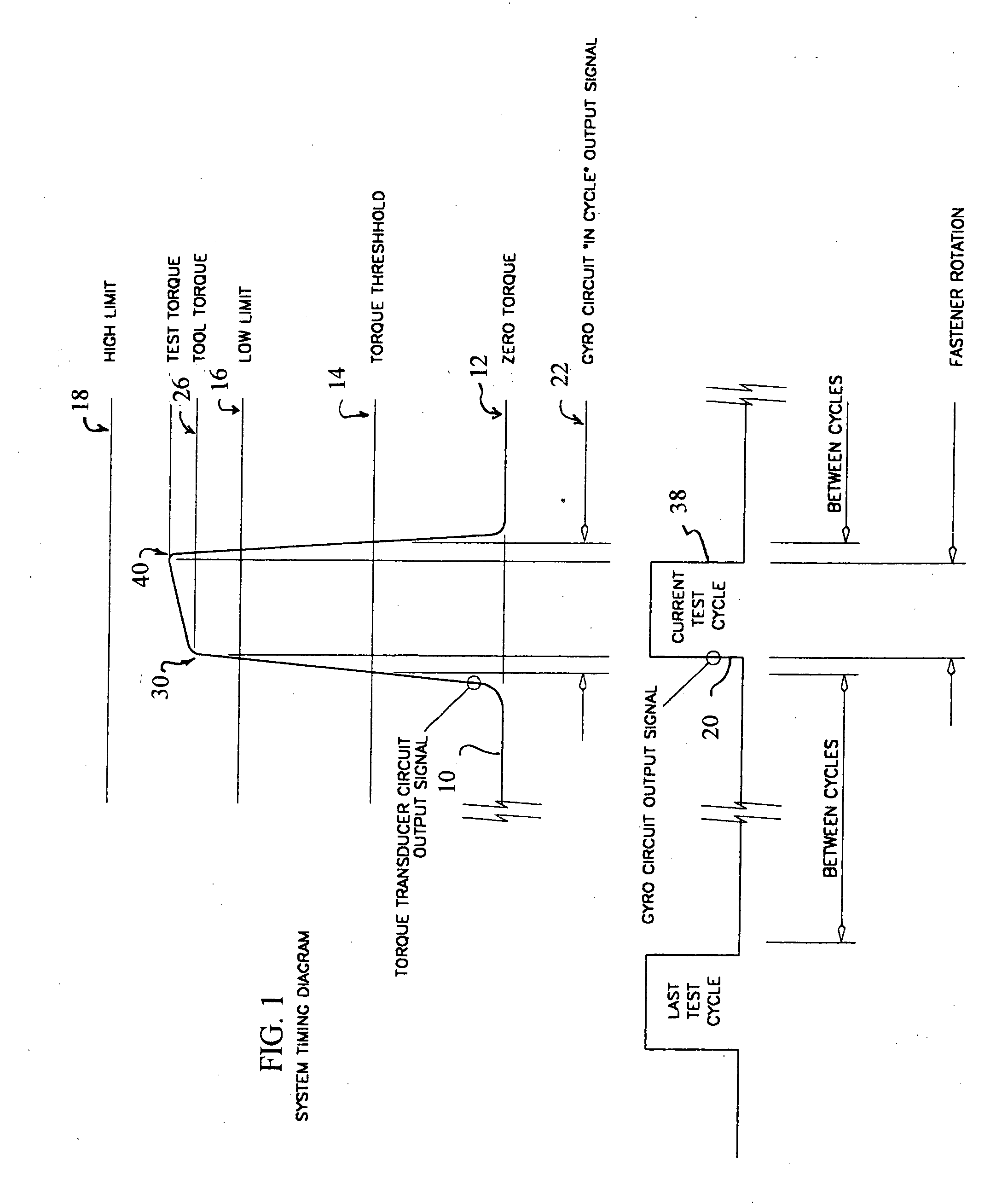
[0008] Referring to FIG. 1, a system timing diagram is illustrated beginning with the tool at rest, so that there is no torque signal 10 being generated by the torque sensors, such as by way of example and not limitation strain gauge sensors, as illustrated along horizontal zero torque line 12. A torque “Threshold” value shown as line 14 can be established by the microprocessor as a percentage of the “Low limit”. The operator can enter a “Low limit” of low torque limit value as illustrated along horizontal line 16 and “High limit” or high torque limit value as illustrated alone horizontal line 18. A test cycle 20 can be started when the operator engages a previously tightened fastener and applies additional tightening torque. The torque signal 10 rises rapidly through the “Torque threshold” value line 14 which activates the data collection portion or subroutine cycle 22 of the microprocessor 24 (seen in FIG. 2). As the increasing torque signal 10 reaches the residual torque value as...


PUM


Abstract

The present invention provides a device for confirming that threaded fasteners have been tightened to the level of torque required by the assembly specification. An apparatus and method is provided for validating or verifying a fastener connection. A wrench or other torque tool can be engaged with a fastener to be tested. A rotation sensor is associated with the wrench for sensing rotation of the fastener and for generating a first output signal. A torque sensor is associated with the wrench for generating a second output signal corresponding to torque being generated by the wrench against the fastener. A processor is in communication with the rotation sensor to receive the first output signal and is in communication with the torque sensor to receive the second output signal. The processor analyzes the first and second output signals in accordance with a control program stored in memory.

Description

FIELD OF THE INVENTION [0001] The present invention relates to an apparatus and method for validating a fastener connection by analyzing output signals from a rotation sensor and a torque sensor in accordance with a control program. BACKGROUND OF THE INVENTION [0002] All assembly operations that incorporate threaded fasteners as clamping devices require that the amount of applied torque be controlled to some tolerance. A low torque condition may not provide enough friction to keep the fastener in place. Application of too much torque can cause an immediate or eventual failure of the fastener. In either case serious safety issues may exist. The most frequently used tools for torque process verification are the dial torque wrench and the click wrench. The dial torque wrench contains either a mechanically driven rotary dial or a strain gauge electronic circuit with a digital display. Although these systems may be very accurately calibrated, use of these tools is a subjective process. W...

Claims


Application Information

Patent Timeline
IPC IPC(8): B25B23/142B25B23/151
CPCB25B23/1425
Inventor LEHNERT, MARK W.JONES, THOMAS M.SCHIAPPACASSE, JOHN M.
Owner LEHNERT MARK W
Learn More