
High pressure container and manufacture thereof

a technology of high-pressure containers and containers, which is applied in the direction of mechanical equipment, vessel construction details, other domestic objects, etc., can solve the problems of metal liner fatigue and inability to eliminate fatigue constraints in metal liner, and achieve the effect of preventing leakag

Inactive Publication Date: 2005-04-28
TOYOTA JIDOSHA KK
View PDF0 Cites 22 Cited by
  • Summary
  • Abstract
  • Description
  • Claims
  • Application Information

AI Technical Summary

Benefits of technology

[0008] It is therefore an object of the present invention to address the aforementioned issues by providing a high pressure container wherein deformation of the metal liner and of the composite material shell are substantially equal, preventing slippage from occurring between the metal liner and the composite material shell.

Problems solved by technology

High pressure containers that employ a metal liner have a problem of fatigue of the metal liner occurring with expansion and contraction of the container during filling with and discharge of gas.
However, with the technology described above, since only a section of the metal liner has a bowed portion that permits appreciable deformation (elastic deformation), the extent of deformation of the metal liner differs from the extent of deformation of the composite material shell, producing slippage between the two.
Accordingly, under high planar pressure shear force is exerted between the metal liner and the composite material shell, producing friction in some slippage portions, while in portions that do not slide the extent of deformation of the metal liner and composite material shell remains substantially the same; accordingly it was not possible to eliminate fatigue constraints in the metal liner.

Method used


Image

  • High pressure container and manufacture thereof
  • High pressure container and manufacture thereof
  • High pressure container and manufacture thereof

Examples


first embodiment

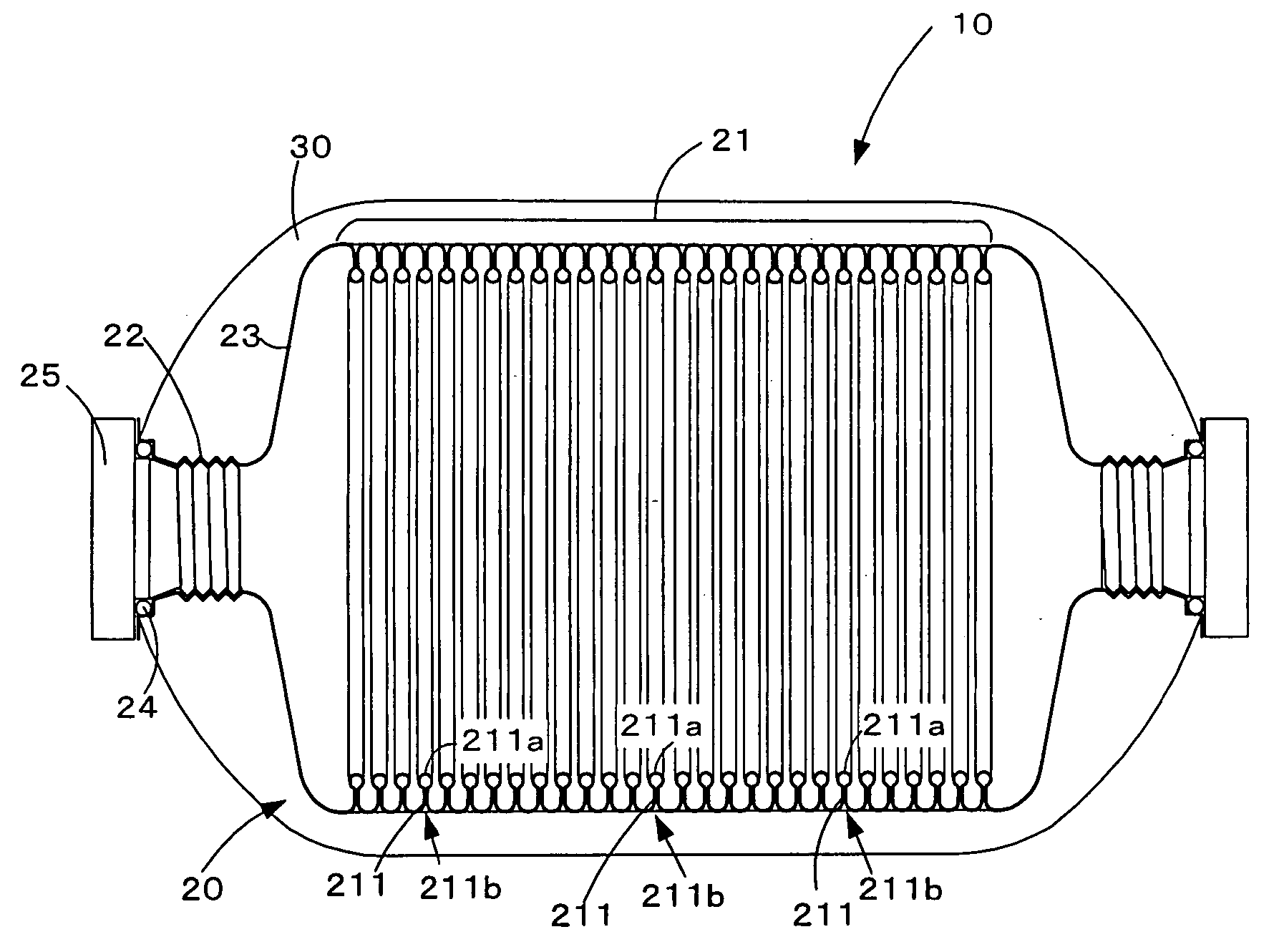
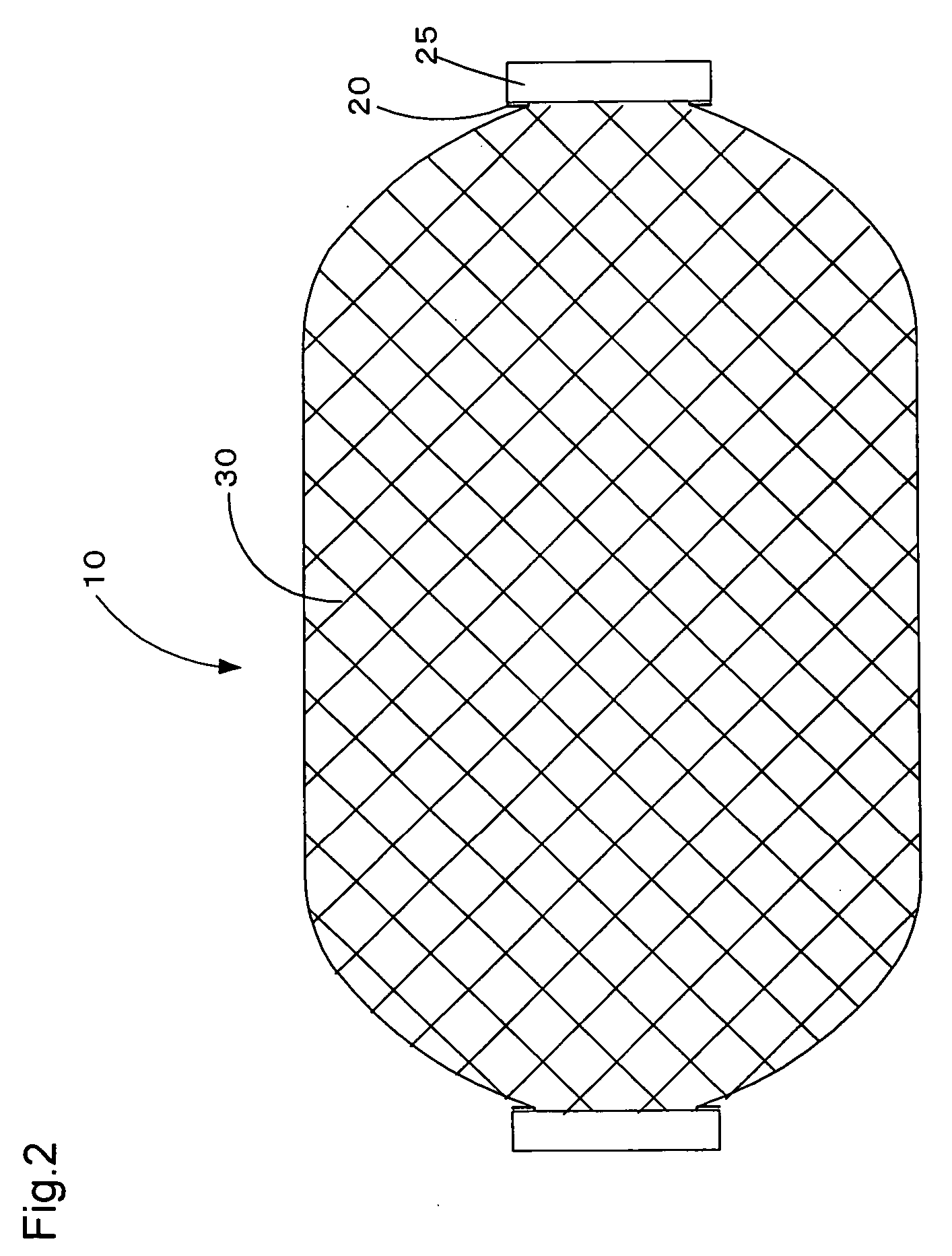
[0060] The following description of the high pressure tank pertaining to the first embodiment makes reference to FIGS. 1-3. FIG. 1 is a partly sectional view illustrating the interior of a high pressure tank pertaining to the first embodiment. FIG. 2 is an illustration showing the exterior of the high pressure tank pertaining to the first embodiment. FIG. 3 is an illustration showing Variation 1 of the high pressure tank pertaining to the first embodiment.

[0061] As shown in FIG. 2, the high pressure tank 10 pertaining to the first embodiment has a cylindrical shape; and as shown in FIG. 1 comprises a metal liner 20 having the required tank shape, and a composite material shell 30 formed on the periphery of the metal liner 20. The metal liner 20 may be fabricated of stainless steel or aluminum, for example.

[0062] The metal liner 20 comprises a cylindrical barrel portion 21, a mouthpiece 22 located at each of two end portions, and a cap portion 23 connecting barrel portion 21 with m...

second embodiment

[0070] The following description of the high pressure tank pertaining to the second embodiment makes reference to FIGS. 4-12. FIG. 4 is a detail illustration showing details of the interior of the high pressure tank pertaining to the second embodiment. FIG. 5 is an illustration showing a first variation of the high pressure tank pertaining to the second embodiment. FIG. 6 is an illustration showing a second variation of the high pressure tank pertaining to the second embodiment. FIG. 7 is an illustration showing a third variation of the high pressure tank pertaining to the second embodiment. FIG. 8 is an illustration showing a fourth variation of the high pressure tank pertaining to the second embodiment. FIG. 9 is an illustration showing a fifth variation of the high pressure tank pertaining to the second embodiment. FIG. 10 is a flowchart showing the manufacturing process for the high pressure container pertaining to the second embodiment. FIGS. 11 and 12 are illustrations showing...

third embodiment

[0084] The following description of the high pressure tank pertaining to the third embodiment makes reference to FIG. 14. FIG. 14 is a detail illustration showing details of the interior of the high pressure tank pertaining to the third embodiment. The metal liner 50 of the high pressure tank 12 pertaining to the third embodiment is formed by a barrel portion constituent element 52 that make up an integrally formed barrel portion 51 having a helical groove that functions as extensible portions, and an end portion constituent element 53 that threadably mates with barrel portion constituent element 52. Other constituent elements of the high pressure tank 12 pertaining to the third embodiment are analogous to constituent elements of the high pressure tank 10 pertaining to the first embodiment; accordingly, these are assigned identical symbols and not described.

[0085] According to the high pressure tank 12 pertaining to the third embodiment, end portion constituent element 53 is thread...


PUM

PropertyMeasurementUnit
Lengthaaaaaaaaaa
Pressureaaaaaaaaaa
Deformation enthalpyaaaaaaaaaa

Abstract

A high pressure tank 10 comprises a metal liner 20 having a desired tank shape; and a composite material shell 30 formed on the periphery of the metal liner 20. The metal liner 20 comprises a cylindrical barrel portion 21, a mouthpiece 22 located at each of two end portions, and a cap portion 23 connecting barrel portion 21 with mouthpiece 22. Extensible portions 211 of bellows configuration are formed along the entire length of the metal liner 20 in the axial (lengthwise) direction. The extensible portions 211 impart elastic action through opening and closing (deformation) of their basal portions 211b, thereby preventing slippage from occurring between the metal barrel portion 21 and the composite material shell 30 when the high pressure tank 10 expands and contracts.

Description

BACKGROUND OF THE INVENTION [0001] 1. Field of the Invention [0002] The present invention relates to a high pressure container, and to a method for manufacturing a high pressure container. [0003] 2. Description of the Related Art [0004] High pressure containers constructed of a metal liner sheathed in a shell of composite material instead of the conventional steel have become commercially viable as high pressure containers, mainly for storing gas. [0005] High pressure containers that employ a metal liner have a problem of fatigue of the metal liner occurring with expansion and contraction of the container during filling with and discharge of gas. With shells of composite material on the other hand, reducing the amount of fiber in order to lower cost and weight has the effect of increasing the amount of expansion and contraction, limiting the number of times that the container is allowed to be filled and discharged. [0006] Thus, there has been proposed a pressurized container having ...

Claims


Application Information

Patent Timeline
IPC IPC(8): B29C70/16F17C1/04B29C70/68B29L22/00F17B1/26F17C1/00F17C1/02F17C1/14F17C1/16
CPCF17B1/26Y02E60/321F17C1/16F17C2201/0104F17C2201/0109F17C2201/0195F17C2201/054F17C2201/056F17C2201/058F17C2203/0604F17C2203/0607F17C2203/0619F17C2203/0621F17C2203/0636F17C2203/0643F17C2203/0646F17C2203/0663F17C2203/067F17C2203/0673F17C2205/0323F17C2205/0397F17C2209/2109F17C2209/2154F17C2209/22F17C2209/221F17C2209/23F17C2221/012F17C2223/035F17C2223/036F17C2260/011F17C2270/0168F17C1/14Y02E60/32F17C1/02
Inventor KIMBARA, MASAHIKOMORI, DAIGOROTSUZUKI, MAKOTOKUMANO, AKIKO
Owner TOYOTA JIDOSHA KK
Learn More