
Increased and variable force and multi-speed clamps

Active Publication Date: 2005-04-21
BLACK & DECKER INC
View PDF99 Cites 25 Cited by
  • Summary
  • Abstract
  • Description
  • Claims
  • Application Information

AI Technical Summary

Benefits of technology

[0012] A fourth aspect of the present invention regards a clamp that includes a first clamping jaw, a support element to which the first clamping jaw is attached, a clamp body having a slot through which the support element passes, a handle grip attached to the clamp body and a trigger handle pivotably mounted to the clamp body. A trigger handle reinforcement is attached to the trigger handle, a driving lever that is movable to a first position where the driving lever engages the support element and causes the support element to move relative to the clamp body and first and second braking levers.
[0018] One or more aspects of the present invention provide the advantage of reducing the time to move a clamping jaw against an object.
[0019] One or more aspects of the present invention provides the advantage of fine tuning the clamping pressure once the clamping jaw contacts the object to be clamped.
[0020] One or more aspects of the present invention provide the advantage of increasing the clamping pressure applied to an object.
[0021] One or more aspects of the present invention provide the advantage of incrementally decreasing the clamping force applied to an object.
[0022] One or more aspects of the present invention provide the advantage of increasing the speed of clamping dependent on the load being applied.

Problems solved by technology

Accordingly, it may take a significant amount of time to clamp an object.
In clamps and spreading clamps similar to those disclosed above, it might be difficult to generate sufficient clamping forces on an object.
In clamps and spreading clamps similar to those disclosed above it also may be difficult to fine-tune the clamping pressure once the clamping jaw contacts the object to be clamped.

Method used


Image

  • Increased and variable force and multi-speed clamps
  • Increased and variable force and multi-speed clamps
  • Increased and variable force and multi-speed clamps

Examples


Embodiment Construction

)

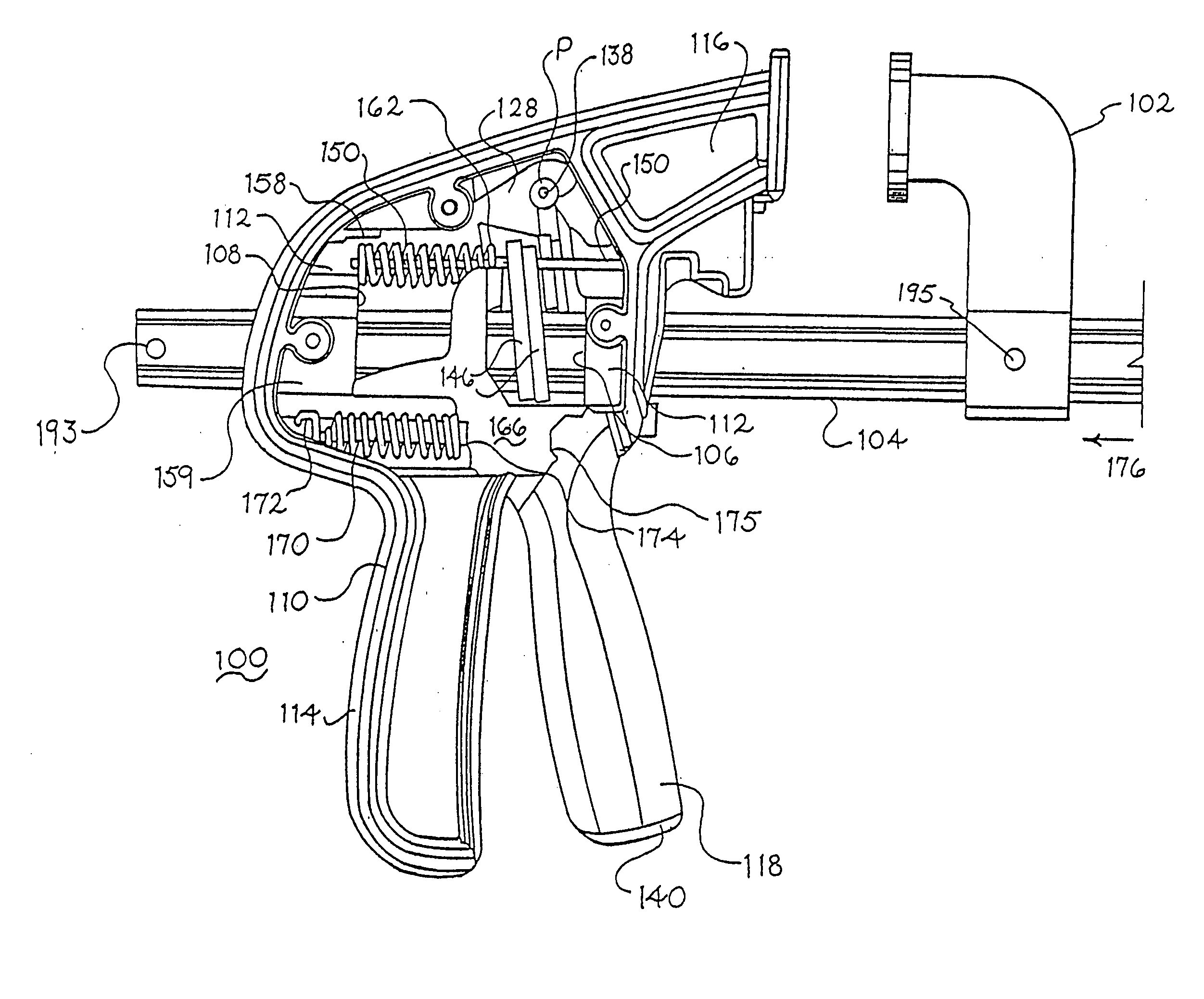
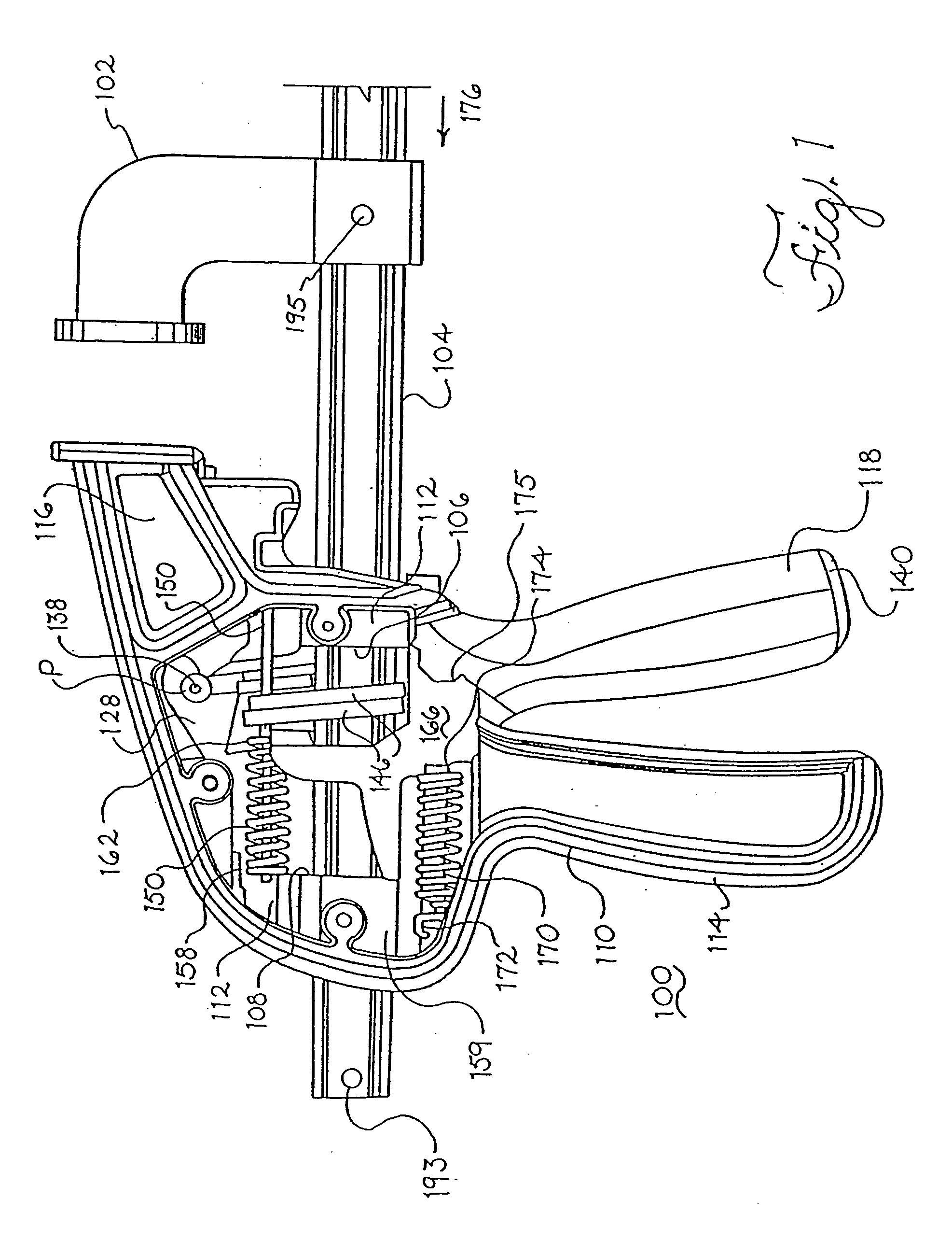
[0052] Referring now to the drawings wherein like reference characters designate identical or corresponding parts throughout the several figures, and in particular FIGS. 1, 14 and 16 show a clamp, such as bar clamp 100. The bar clamp 100 includes a clamping jaw 102 connected to a support element, such as a rod or a bar 104. The clamping jaw 102 may be fixed to the rod or bar 104 via a pin in the manner disclosed in U.S. Pat. No. 4,926,722 or it may have a detachable structure such as disclosed in U.S. patent application Ser. No. 09 / 036,360, the entire contents of each of which are incorporated herein by reference. The bar 104 is slidably supported in a proximal slot or bore 106 and a distal slot or bore 108, each of which passes through a handle / grip assembly 110.

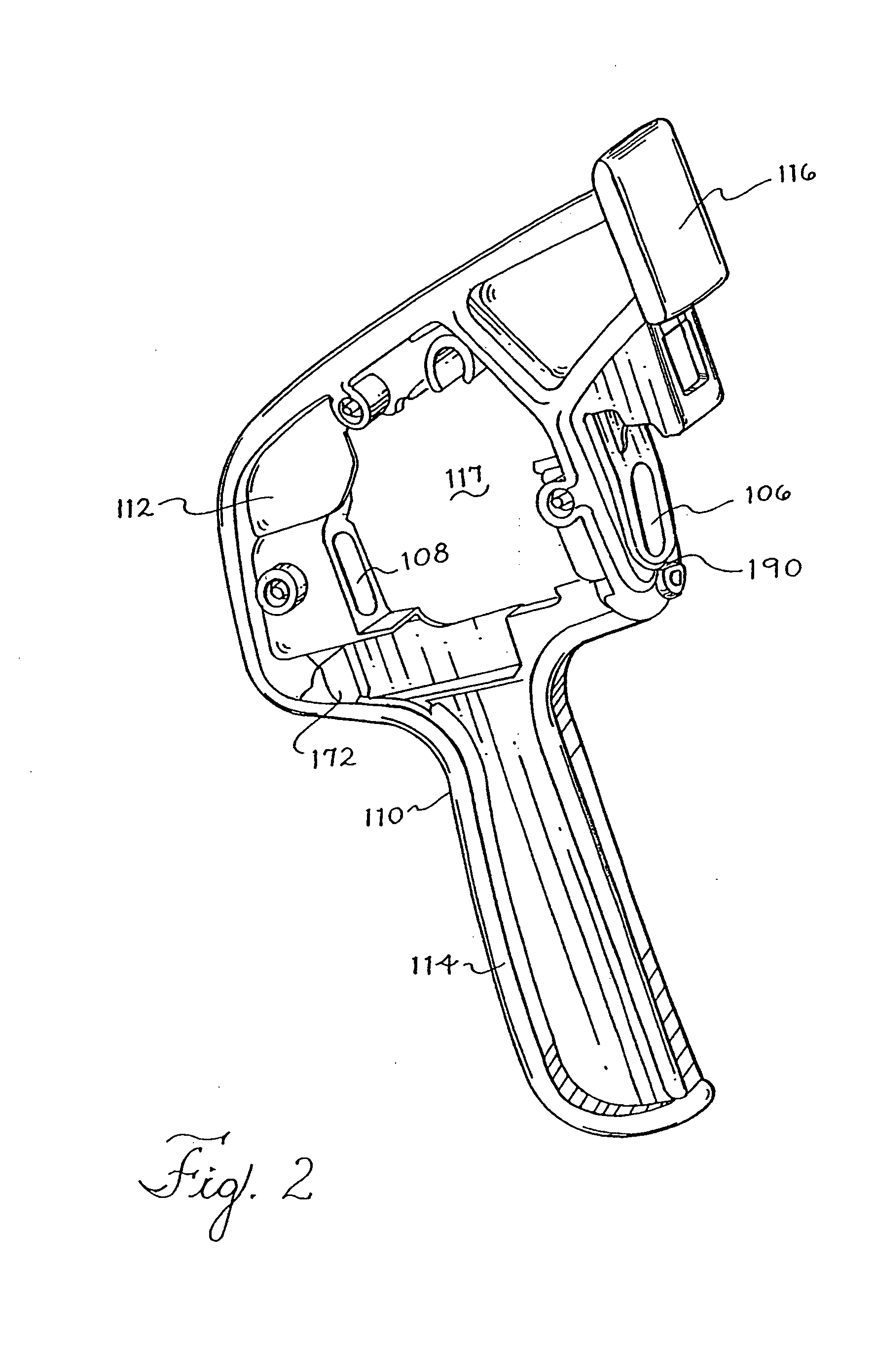
[0053] As shown in FIGS. 2 and 3, the handle / grip assembly 110 includes a clamp body 112 through which the slots 106 and 108 pass, a handle grip 114 attached to the clamp body 112 on one side of the slots 106 and 108, and...


PUM

PropertyMeasurementUnit
Lengthaaaaaaaaaa
Timeaaaaaaaaaa
Forceaaaaaaaaaa

Abstract

A method of operating a clamp (100) that includes a first clamping jaw (102), a support element (104) to which the first clamping jaw is attached and a trigger handle (118) pivotably mounted to a clamp body (112). The method includes actuating the trigger handle causing the first clamping jaw to experience incremental motion and varying the incremental motion as a function of a load encountered by the support element by varying an effective lever arm of the trigger handle by moving a fulcrum point into contact or out of contact with the trigger handle based on the load.

Description

BACKGROUND OF THE INVENTION [0001] 1. Field of the Invention [0002] This invention relates to a clamp that varies and / or increases the force applied to a clamped object and varies the speed of clamping an object. [0003] 2. Discussion of Related Art [0004] Bar clamps for clamping objects into position are well known in the art. In recent years, advances have been made in bar clamps that enable them to be operated by a single hand. An example of such a bar clamp is disclosed in U.S. Pat. No. 4,926,722 which discloses a trigger mechanism to move a movable clamping jaw toward a fixed clamping jaw. The movable clamping jaw is attached to a moving bar. [0005] Spreading clamps that are operable by a single hand are also well known, such as described in U.S. Pat. No. 5,009,134. Again, the movable jaw is attached to a bar. [0006] In bar clamps and spreading clamps similar to those disclosed above, it may take a large number of strokes of the trigger mechanism to move a clamping jaw against a...

Claims


Application Information

Patent Timeline
IPC IPC(8): B25B5/06
CPCY10T29/49998B25B5/068
Inventor CICENAS, CHRIS W.MCKEAN, CHARLES R.CHERVENAK, THOMAS M.FULLER, ANTHONY B.
Owner BLACK & DECKER INC
Learn More