
Display control

a control method and display technology, applied in the field of display control, can solve the problems of large power consumption of the liquid crystal display provided in the notebook pc, complicated switching operations in the conventional maximum brightness changing operation, and long operation time, and achieve the effect of efficiency in the change of the maximum brightness of the display

Inactive Publication Date: 2005-04-14
LENOVO (SINGAPORE) PTE LTD
View PDF8 Cites 6 Cited by
  • Summary
  • Abstract
  • Description
  • Claims
  • Application Information

AI Technical Summary

Benefits of technology

[0009] Accordingly, a purpose of the present invention is to provide a display controller designed so that the maximum brightness of a display can be changed with efficiency while addition of any new operating member for an operation to change the maximum brightness of the display is avoided, a display control method, and a display control program product for the display controller.
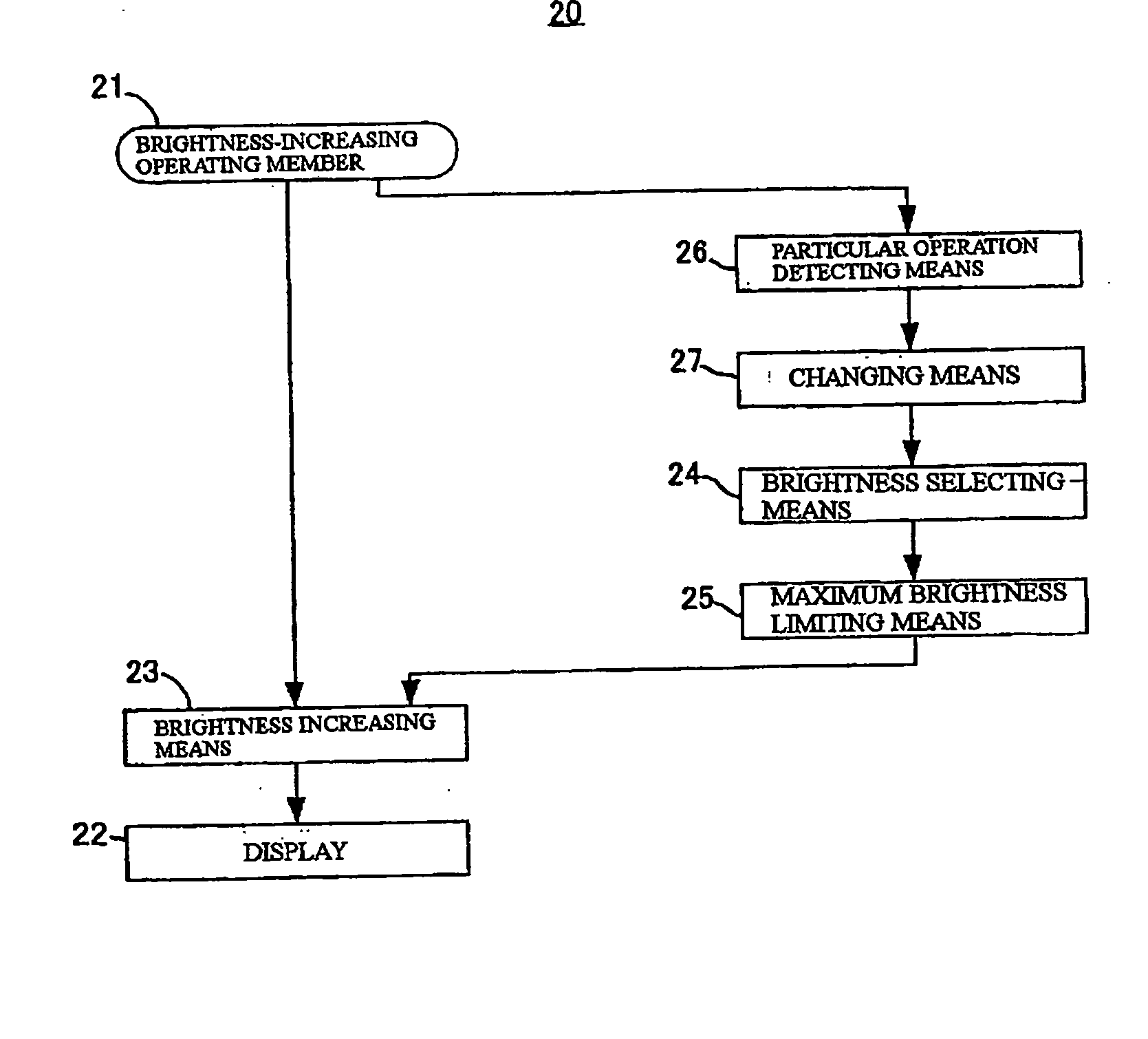
[0035] According to the present invention, a particular operation in operations performed on the operating member in a predetermined manner by a user when the user increases the brightness of a display one step is regarded as a user's request for increasing the maximum brightness. When this operation is detected, the maximum brightness of the display is increased. The need for adding an operating member for changing the maximum brightness separately from the operating member for changing the brightness can be eliminated and the troublesome operation to be performed by the user to start a predetermined application can be omitted.

Problems solved by technology

The amount of power consumed by an LCD (liquid crystal display) provided in a notebook PC is large.
Switching operations in conventional maximum brightness changing operations are complicated and require a long operation time since they are a process in which a user starts a brightness changing application and inputs a value for the brightness level according to his / her preference, and a menu at a low hierarchical level is displayed, and the like.
On the other hand, addition of an operating member for changing the maximum brightness, for example, to a keyboard of a notebook PC is not preferable because of restrictions in terms of space and cost.

Method used


Image

  • Display control
  • Display control
  • Display control

Examples


Embodiment Construction

[0050] While the present invention will be described more fully hereinafter with reference to the accompanying drawings, in which a preferred embodiment of the present invention is shown, it is to be understood at the outset of the description which follows that persons of skill in the appropriate arts may modify the invention here described while still achieving the favorable results of this invention. Accordingly, the description which follows is to be understood as being a broad, teaching disclosure directed to persons of skill in the appropriate arts, and not as limiting upon the present invention.

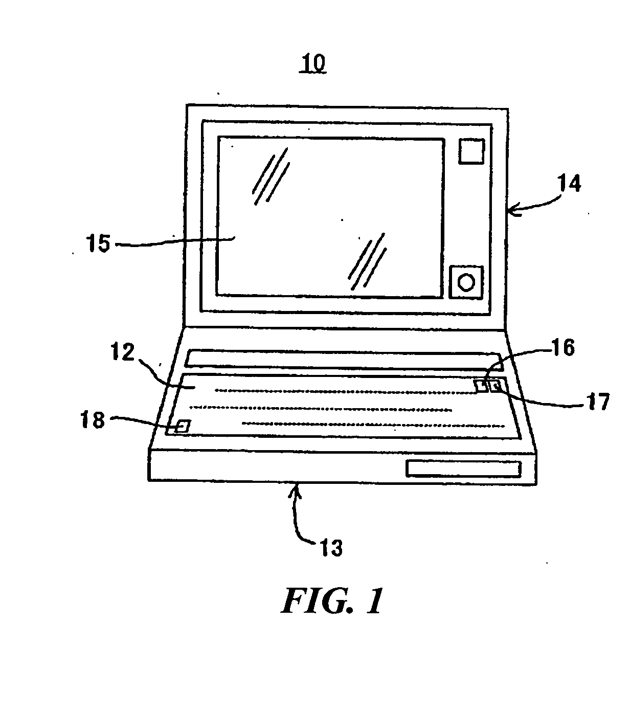
[0051] Referring now more particularly to the accompanying drawings, in which like numerals indicate like elements or steps throughout the several views, FIG. 1 is a perspective view of a notebook PC 10. The notebook PC 10 has a main body 13 having a keyboard 12 provided in its upper surface, and a lid 14 having its lower side portion rotatably connected to an inner side portion of th...


PUM


Abstract

A maximum brightness limiting mechanism limits the maximum brightness of the display to a brightness selected by a brightness selecting mechanism. If a user operates the brightness-increasing operating member a number of times in a unit time equal to or larger than a predetermined number of times when the brightness of the display is a second brightness, a particular operation detecting mechanism detects this operation as a particular operation. Upon this detection, the brightness selecting mechanism changes the selected brightness from the second brightness to a first brightness.

Description

BACKGROUND OF THE INVENTION [0001] The present invention relates to a controller, a control method, and a control program product for a display device provided in a portable PC (personal computer) for example and, more particularly, to a display controller, a display control method, and a display control program product for suitably controlling the maximum brightness of a display. [0002] Notebook PCs can operate by power supplied from either of an external alternating-current power supply and an incorporated chargeable battery. The amount of power consumed by an LCD (liquid crystal display) provided in a notebook PC is large. In a typical notebook PC, therefore, the LCD is operated at a suitable low brightness when battery power is used, while it is operated at a high brightness when power from an external alternating-current power supply is used. The battery operating time is thereby increased. [0003] In the conventional notebook PCs, the brightness of the LCD is automatically fixe...

Claims


Application Information

Patent Timeline
IPC IPC(8): G09G3/20G09G3/32G09G5/00G09G5/10
CPCG09G5/10G09G2330/021G09G2320/0626G09G2320/0606
Inventor OZEKI, NORHITO
Owner LENOVO (SINGAPORE) PTE LTD
Learn More