
RFI canceller

Inactive Publication Date: 2005-04-07
ZARLINK SEMICON LTD
View PDF5 Cites 17 Cited by
  • Summary
  • Abstract
  • Description
  • Claims
  • Application Information

AI Technical Summary

Benefits of technology

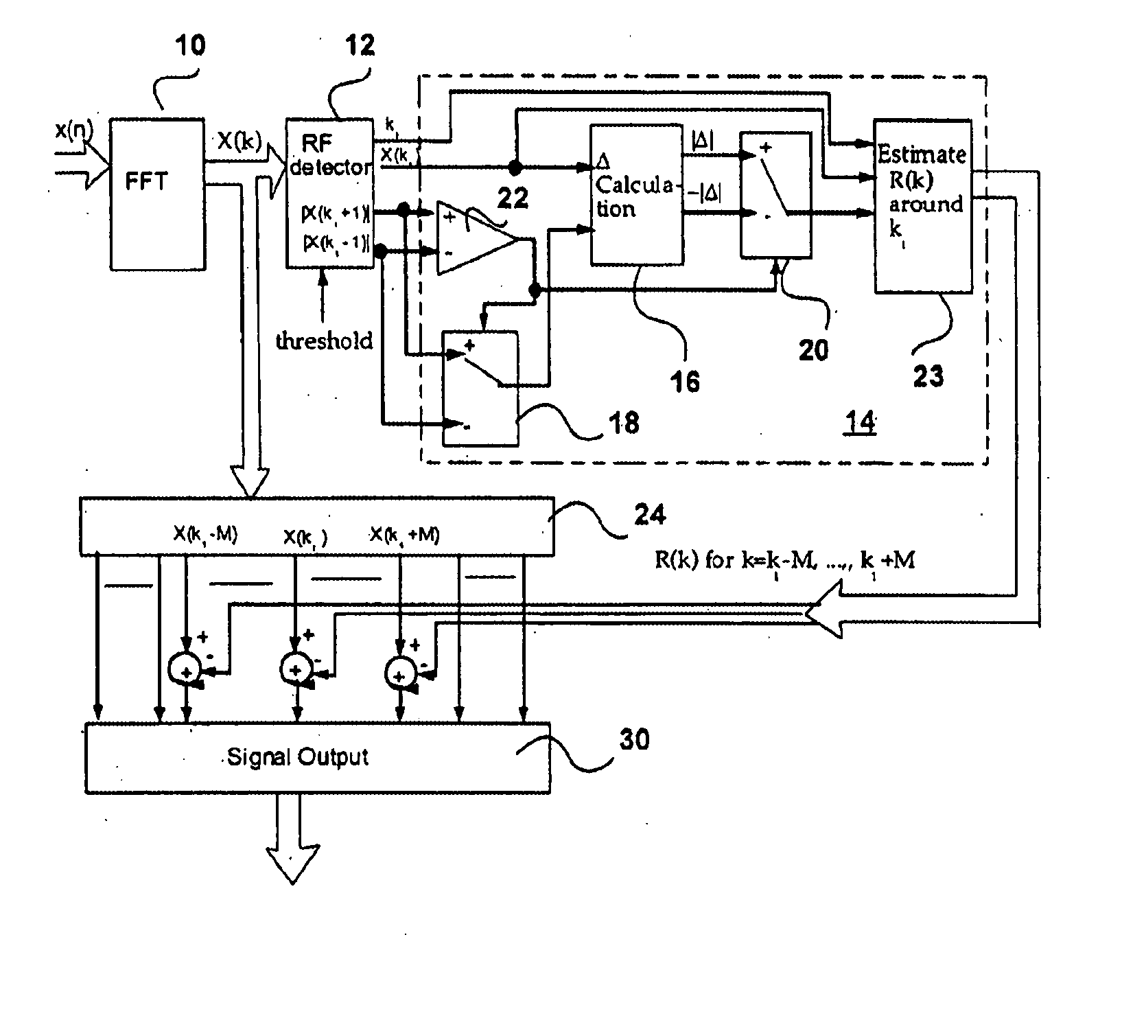
In this invention, the novel RFI cancellation technique can potentially reduce the RF interference by an extra 30 dB. The method is based on the fact that the RFI is a narrow band signal and its strength and location will provide enough information to predict its interference to other DMT subchannels, and hence can be subtracted from received signal in these subchannels.

Problems solved by technology

In a DMT based DSL system, radio frequency interference (RFI) is an important interference source and its cancellation is a difficult task.
On the other hand, RFI is normally a narrow band interference which seems not affect DMT signal too much.
However, due to the FFT window effect, the narrow band RF signal may not be orthogonal to DMT signals and will cause interference to its neighboring subchannels.
Indeed, since RFI could be 30 dB above the DMT signal, its sidelobe may jam many DMT subchannels.
However, RF interference may still cause significant performance degradation to its neighboring 10-20 subchannels due to its high interference strength.

Method used


Image

  • RFI canceller
  • RFI canceller
  • RFI canceller

Examples


Embodiment Construction

In order to fully understand the invention it will be helpful to understand the theory on which it is based. Let's assume that RFI is a narrow band signal with frequency located at location related with FFT as ω0=2⁢π⁢(k1+Δ)N,

−0.5≦Δ≦0.5 and k1 is an integer and its time domain waveform looks like

Aej(ω0n+θ)

The Fourier transform of such narrow band signal can be expressed as R⁡(k)≈⁢A⁢ ⁢ⅇj⁢ ⁢θ⁢∑n⁢ ⁢ⅇj⁢ ⁢2⁢π⁢(k1+Δ)N·ⅇ-j⁢ ⁢2⁢π⁢ ⁢n⁢kN=⁢ⅇj⁢ ⁢π⁡[Δ⁡(1-1N)+k-k1N]⁢sin⁢ ⁢π⁢ ⁢Δsin⁢ ⁢π⁡(ΔN-k-k1N)⁢A⁢ ⁢ⅇj⁢ ⁢θ

where the assumption that the window is close to rectangular even with a small edge roll off is applied. See, T1E1.4 / 2001-009R2 referred to above.

At k=k1, we have R⁡(k1)=ⅇj⁢ ⁢π⁡[Δ⁡(1-1 / N)]·sin⁢ ⁢π⁢ ⁢Δsin⁡(π⁢ ⁢Δ / N)·A⁢ ⁢ⅇj⁢ ⁢θ

which is the peak location in the entire frequency subchannels if RFI present. At k≠k1 but k≈k1, we⁢ ⁢have R⁡(k)=⁢R⁡(k1)⁢ⅇj⁢ ⁢π⁢k-k1N⁢sin⁢ ⁢π⁡(Δ / N)sin⁢ ⁢π⁡(Δ / N-(k-k1) / N)≈⁢R⁡(k1)⁢ΔΔ-(k-k1)(1)

where we assume N is large comparing with (k−k1).

Now Δ can be calculate...


PUM


Abstract

Narrow band RF interference in a modulated signal carried on a plurality of subchannels is carried out by detecting RF interference in the subchannels, identifying a subchannel where the magnitude of the RF interference has a predetermined characteristic, determining the value of the magnitude of the RF interference with the predetermined characteristic, determining the value of the magnitude of the RF interference in neighboring subchannels, estimating the value of the magnitude of the RF interference the remaining subchannels from the determined values, and subtracting the estimated values of the magnitude of the RF interference from the signals in the corresponding remaining subchannels.

Description

FIELD OF THE INVENTION This invention relates to the field of communications, and in particular to an RFI canceller suitable for use, for example, in a discrete multitone (DMT) digital subscriber line (DSL) system. BACKGROUND OF THE INVENTION DMT is a modulation scheme used in DSL systems, wherein a wideband modulated signal is carried on a number of discrete carriers or tones. Each tone constitutes a subchannel that is independently modulated to carry part of the bits in the information. In a DMT based DSL system, radio frequency interference (RFI) is an important interference source and its cancellation is a difficult task. The DMT signal is a wide band modulated signal with each subchannel being modulated independently to carry part of information bits. In the receiver, FFT (Fast Fourier Transform) is normally used to separate subchannels which are orthogonal with each other in frequency domain. See, “Very-high-bit-rate Digital Subscriber Line (VDSL) Metallic Interface Part 1:...

Claims


Application Information

Patent Timeline
IPC IPC(8): H04B1/707H04L27/26
CPCH04L27/2647H04B1/7102
Inventor JIN, GARY QU
Owner ZARLINK SEMICON LTD
Learn More