Eureka AIR delivers breakthrough ideas for toughest innovation challenges, trusted by R&D personnel around the world.

System and method for hemisphere disambiguation in electromagnetic tracking systems

Inactive Publication Date: 2005-03-24
GE MEDICAL SYST GLOBAL TECH CO LLC
View PDF40 Cites 33 Cited by
  • Summary
  • Abstract
  • Description
  • Claims
  • Application Information

AI Technical Summary

Benefits of technology

[0022] Certain embodiments of the present invention also provide a method of alleviating hemisphere ambiguity in an electromagnetic tracking system. The method includes disposing a transmitter coil trio configured to generate a magnetic field on a first body, disposing a receiver coil trio configured to sense the magnetic field generated by the transmitter coil trio on a second body, and mounting a single receiver coil on the second body a fixed and known distance away from the receiver coil trio so that movement between the transmitter coil trio, the receiver coil trio and the single receiver coil is asymmetrical resulting in different magnetic field measurements detected by the receiver coil trio and the single receiver coil at every position during movement. A constant orientation of the receiver coil trio and the single receiver coil is maintained during movement. The method also includes determining two positions (x, y, z) and (−x, −y, −z), predicting a received field at the two positions using a field model of the single receiver coil, and determining which predicted field better matches the magnetic field detected by the receiver coil trio and the single receiver coil.

Problems solved by technology

However, medical practitioners often do not have the use of medical imaging systems when performing medical procedures.
The use of medical imaging systems for instrument tracking may be limited for health and safety reasons (e.g., radiation dosage concerns), financial limitations, physical space restrictions, and other concerns, for example.
That is, a tracking system may be used in other settings where the position of an instrument in an object or an environment is difficult to accurately determine by visual inspection.
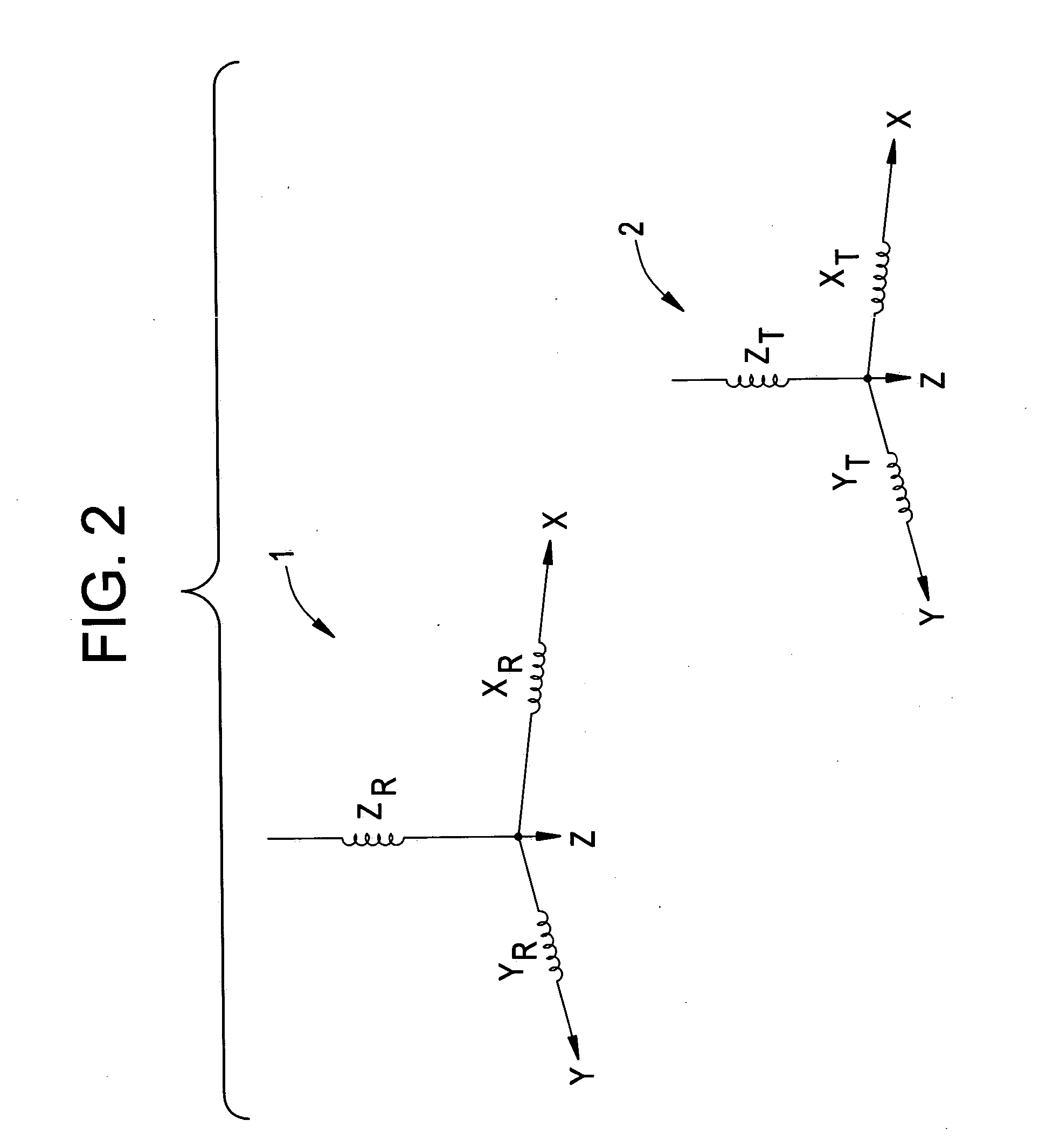
A limitation of a system using the receiver coil trio 1 and the transmitter coil trio 2 is hemisphere ambiguity.
Spacing the receiver coil trios a suitable distance apart takes up space.
The medical instrument may not be large enough to accommodate the two receiver coils positioned a suitable distance apart.
Further, the use of additional receiver coil trios on the medical instrument may be bulky, obtrusive, or otherwise awkward.

Method used


Image

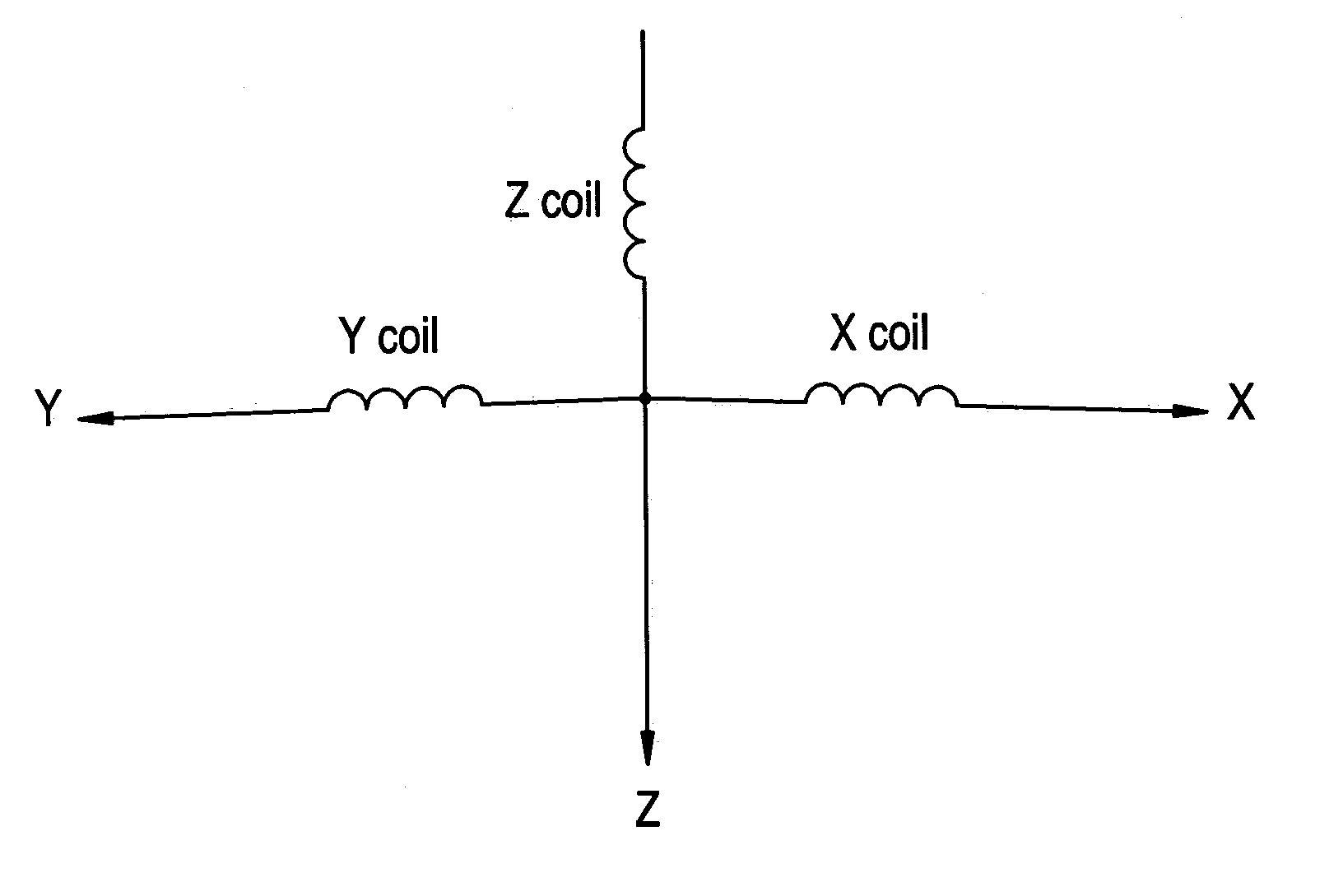
  • System and method for hemisphere disambiguation in electromagnetic tracking systems
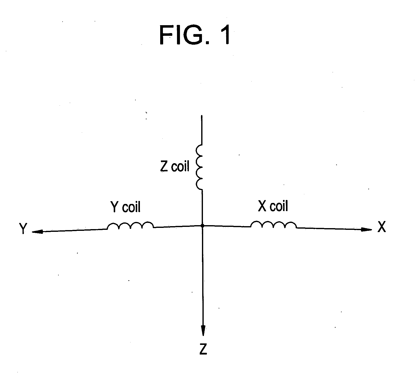
  • System and method for hemisphere disambiguation in electromagnetic tracking systems
  • System and method for hemisphere disambiguation in electromagnetic tracking systems

Examples


Embodiment Construction

[0035]FIG. 4 illustrates an electromagnetic tracking system 10 according to an embodiment of the present invention. The system 10 includes a headset 12 mounted on a patient 14, a medical instrument 16, a control system 18, and a display 20. The control system 18, which is in electrical communication with the medical instrument 16, the headset 12 and the display 20, includes a position detection unit 22, a registration unit 24, and an image storage unit 26. The image storage unit 26 stores sets of prerecorded images such as CAT, MRI, or PET scan images. Each set of images may be taken along, for example, coronal, sagittal or axial directions. The system 10 operates to track the medical instrument 16 with respect to the headset 12 through various methods known in the art.

[0036] The system 10 also includes a receiver assembly positioned on the headset 12 defined by a receiver coil trio 28 and a single coil 30 located a fixed distance away from the receiver coil trio 28. The receiver a...


PUM


Abstract

An electromagnetic tracking system includes a transmitter assembly having a transmitter coil trio, a receiver assembly having a receiver coil trio, and a single coil mounted on one of the receiver assembly and the transmitter assembly. The single coil is positioned a fixed and known distance away from one of the receiver coil trio and the transmitter coil trio. When the receiver assembly is moved relative to the transmitter assembly, relative motion between at least two of the transmitter coil trio, the receiver coil trio and the single coil is asymmetrical, thereby generating different magnetic fields therebetween. The sensed magnetic field, or mutual inductances, between the transmitter assembly and the receiver assembly is different at each position. Thus, each position within a detectable area of the system is distinguishable.

Description

BACKGROUND OF THE INVENTION [0001] The present invention generally relates to an electromagnetic tracking system. In particular, the present invention relates to a system and method for hemisphere disambiguation with respect to an electromagnetic tracking system. [0002] Many medical procedures involve a medical instrument, such as a drill, a catheter, scalpel, scope, shunt or other tool. In some cases, a medical imaging or video system may be used to provide positioning information for the instrument. However, medical practitioners often do not have the use of medical imaging systems when performing medical procedures. The use of medical imaging systems for instrument tracking may be limited for health and safety reasons (e.g., radiation dosage concerns), financial limitations, physical space restrictions, and other concerns, for example. [0003] Medical practitioners, such as doctors, surgeons, and other medical professionals, often rely upon technology when performing a medical pro...

Claims


Application Information

Patent Timeline
IPC IPC(8): G01V3/10
CPCA61B19/5244G01V3/104A61B2019/5272A61B2019/5251A61B34/20A61B2034/2051A61B2034/2072
Inventor ANDERSON, PETER TRANEUS
Owner GE MEDICAL SYST GLOBAL TECH CO LLC
Why Eureka
Eureka Blog
Learn More