
Temperature compensating optical component packaging structure

a packaging structure and optical component technology, applied in the field of packaging structures, can solve the problems of increasing the requirements for controlling and stabilizing the center wavelength, the dependence of bragg gratings, and the large limitation of the widespread use of bragg gratings, so as to facilitate customization of spacing, increase the overall size of the structure, and accurate thermal compensation

Active Publication Date: 2005-03-17
ITF TECH
View PDF7 Cites 2 Cited by
  • Summary
  • Abstract
  • Description
  • Claims
  • Application Information

AI Technical Summary

Benefits of technology

It is therefore a general object of the present invention to provide such an improved structure for athermally and adjustably supporting a segment of optical fiber having an optical component attached thereto.
In accordance with the present invention, there is also provided a packaging structure for supporting a segment of optical fiber, the fiber defining a fiber longitudinal axis, a fiber first end and an opposed fiber second end, the fiber being provided with an optical component optically coupled thereto between the fiber first and second ends for modifying the optical characteristics of an optical signal traveling therethrough, the modification of the optical characteristics of the optical signal imputable to the optical component being at least in part dependant on the temperature and strain conditions imparted on the optical component, the optical fiber being attachable about a fiber first attachment point and a fiber second attachment point to the packaging structure, the fiber first and second fiber points being positionable respectively between the fiber first end and the optical component and between the fiber second end and the optical component; the packaging structure comprising: a housing having a generally hollow housing body, the housing body defining a housing body first end and a substantially opposed housing body second end; a first component mounted on the housing substantially adjacent the housing body first end, the first component being provided with a first channel extending therethrough for receiving a portion of the fiber, the first channel defining a first channel axis, the first channel axis being in a generally collinear relationship relative to the fiber longitudinal axis, a fiber-to-first component attachment means extending between the fiber and the first component for attaching the fiber first attachment point to the first component; a fiber-to-housing attachment means extending between the fiber and the housing for attaching the fiber second attachment point to the housing; the fiber first and second attachment points being spaced relative to each other in a direction generally parallel to the fiber longitudinal axis by an adjustable fiber point spacing; a per-attachment customization means associated with the structure for allowing customization of the length of the fiber point spacing during attachment of the fiber first and second attachment points respectively to the first component and the housing; a post-attachment customization means associated with the structure for allowing customization of the length of the fiber point spacing after attachment of the fiber first and second attachment points respectively to the first component and the housing; the housing being made of a housing material having a housing coefficient of thermal expansion, the first component being made out of a first component material, the housing and first component coefficients of thermal expansion being selected so as to compensate for the dependency of the optical characteristics of the optical signal imputable to the optical component.

Problems solved by technology

The dependence of Bragg gratings to load induced stresses and often more importantly to temperature is however disadvantageous when the Bragg grating is used in applications such as communication systems often requiring a good stability of the spectral response thereof.
Indeed, as optical channel space becomes narrower for higher capacity communication systems, the requirements have become increasingly stringent for controlling and stabilizing the center wavelength of Bragg gratings.
Since commercial communication systems and advanced communication networks typically operate over an extensive range of temperature, the thermal dependence of Bragg gratings greatly limits their widespread use.
Intrinsic methods and devices have proven to be unsuitable for telecommunication applications wherein the spectral response of each individual Bragg gratings must be stabilized against relatively small temperature fluctuations.
Although active thermal stabilization is relatively effective, it nevertheless suffers from severe drawbacks including costly implementation, potentially costly power consumption and inherent complexity potentially leading to reliability problems.
However, the optical parameters vary slightly with temperature and, hence, athermalization is only achieved at a given temperature around which the Bragg wavelength displays a generally parabolic variation with temperature.
Although, theoretically interesting, structure using materials having an intrinsic negative coefficient of thermal expansion suffer from numerous drawbacks including that suitable materials are relatively scarce or difficult to produce and, hence, relatively expensive Also, the coefficient of thermal expansion of such materials needs to be precisely matched to the properties of the optical fiber, hence requiring a precise control of the material formulation.
Furthermore, the coefficient of thermal expansion of such materials needs to be relatively constant from one sample of material to another that may prove to be difficult to achieve in practice.
In other words, it is particularly difficult to provide a negative coefficient of thermal expansion material that precisely compensates for temperature variations without any overcompensation or undercompensation.
One of the major drawbacks associated with conventional differential expansion-type temperature compensation structures relates to the fact that such structures are deprived of a suitable and reliable means for adjusting the value of the Bragg wavelength.
Although the structure disclosed in the hereinabove-mentioned patent application publication provides some improvement over other prior art devices by incorporating relatively fine-tunable resonant wavelength adjustment means, it nevertheless suffers from other drawbacks.
One of these drawbacks is the inherent interdependency between the adjustment of the tension imparted on the fiber and a corollary adjustment of the spacing between the anchor points.
The inability to allow for independent adjustment of the Bragg wavelength and of the wavelength excursion by temperature change may prove to be unsatisfactory in numerous situations.
For example, some components such as certain types of GFFs only allow for a relatively small margin of error for both the tuning of the Bragg wavelength and athermicity.
Consequently, in situations such as when the coefficient of thermal expansion of the materials varies from one structure to another or when the structure needs to be manufactured using materials exhibiting coefficients of thermal expansion different from that for which the device has been designed or used, the displacement range of the thread may prove insufficient to allow for adequate tuning or, alternatively, the threaded portion of the threaded member may need to be oversized in order to allow for adequate tuning.
This, in turn, may lead to potentially inacceptable increases in the overall size of the structure.
The structure disclosed in U.S. Patent Application Publication No. 2002 / 0141700 A1 also suffers from failing to provide a means for ensuring precise, ergonomic and reliable positioning of the attachment components used for fixing the fiber to the members about the anchoring points during assembly.
Since the performance of the structure is highly dependent on the repeatability of the manufacturing process, this may prove to be a major drawback.
As a result, more stringent manufacturing is required thus leading to reduced yields and limited performance.
In addition, the design of the above-mentioned device does not afford a post-manufacturing adjustment to accurately tune the response of the grating to precisely and repeatably achieve the desired temperature sensitivity specifications.
Although the device disclosed in U.S. Pat. No. 6,377,727 allows for customization of the spacing between the fiber anchoring points, it fails to teach and, in fact, teaches away from providing a means for adjusting the spacing between the anchoring points and, hence, the tension within the fiber once the fiber is anchored to the structure.
Hence, this structure also fails to provide means for allowing independent adjustment of both the central wavelength and the wavelength excursion per temperature differential.
The structure also suffers from failing to provide a means for allowing accurate, ergonomic and reliable attachment of the fiber to the structure about the fiber anchoring points.

Method used


Image

  • Temperature compensating optical component packaging structure
  • Temperature compensating optical component packaging structure
  • Temperature compensating optical component packaging structure

Examples


Embodiment Construction

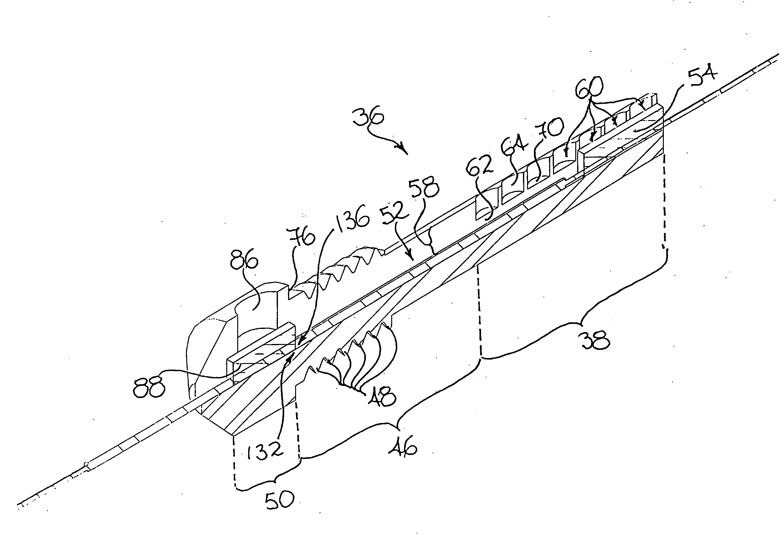
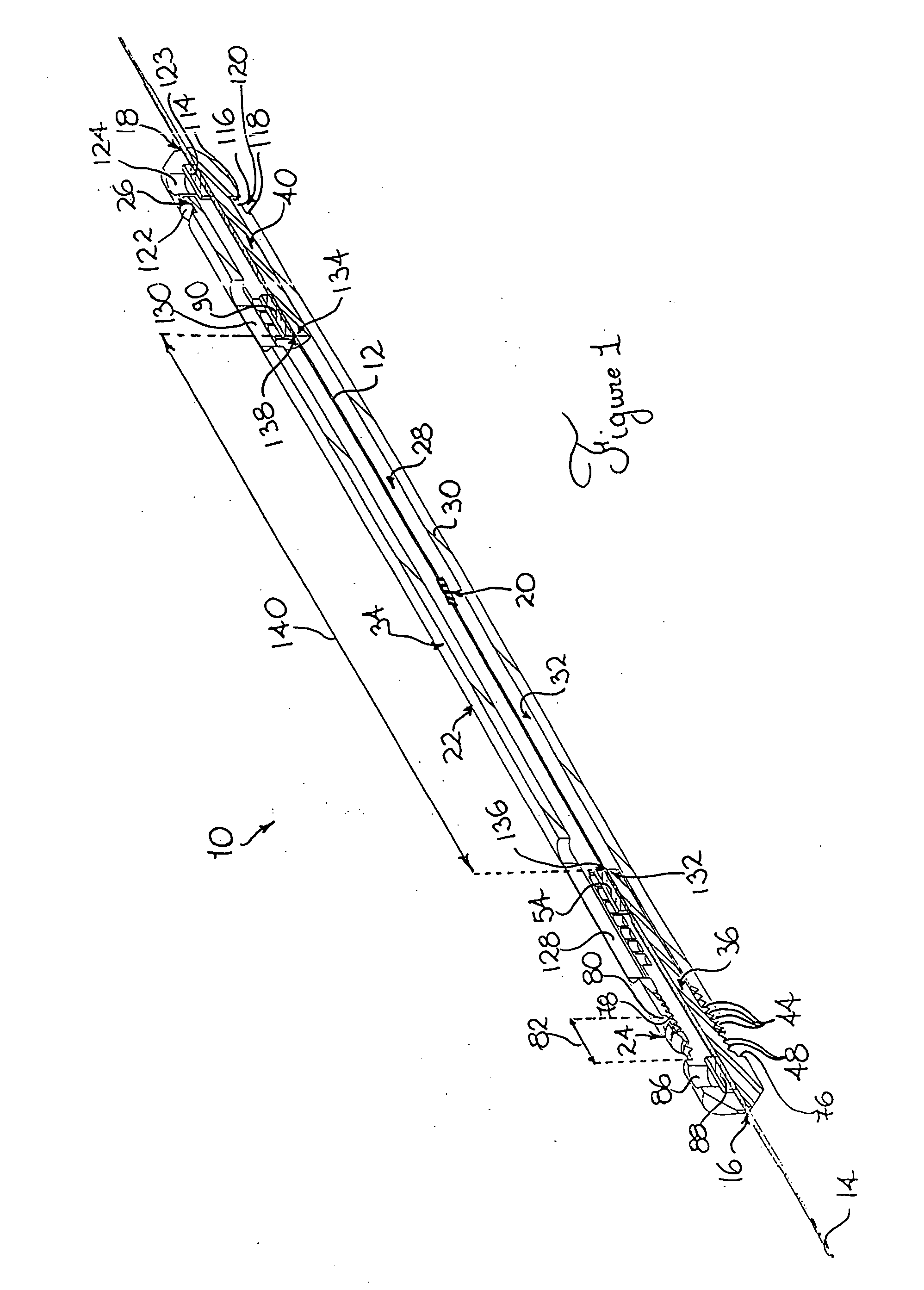
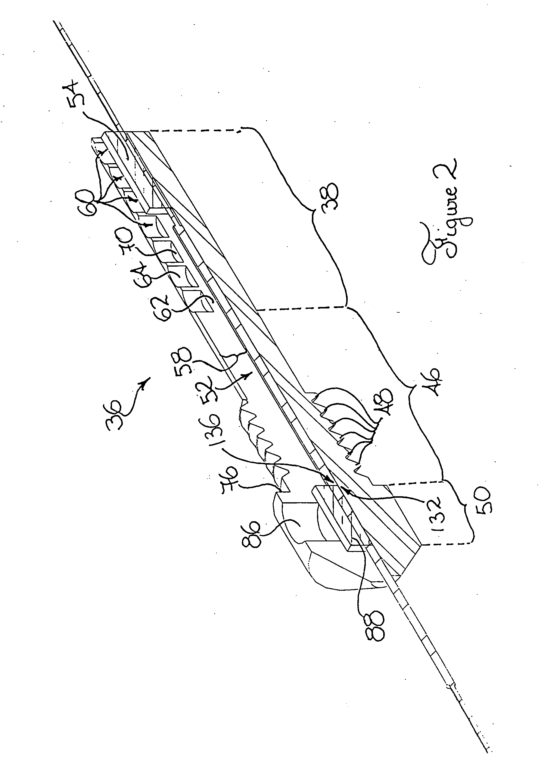
Referring to FIG. 1, there is shown a temperature compensating optical component packaging structure 10 in accordance with an embodiment of the present invention. The packaging structure 10 is typically used for athermally and adjustably supporting a segment of optical fiber 12. The segment of optical fiber 12 defines a fiber longitudinal axis 14, a fiber first end 16 and an opposed fiber second end 18.

The segment of optical fiber 12 is typically provided with an optical component 20 optically coupled thereto between the fiber first and second ends 16, 18 for modifying the optical characteristics of an optical signal traveling therethrough. The optical component 20 is such that the modifications imputable thereto of the optical characteristics of the optical signal are, at least in part, dependent on the temperature and strain conditions imparted on the optical component 20.

Typically, the optical component 20 includes optical fiber Bragg gratings. In situations wherein the opti...


PUM


Abstract

A packaging structure for supporting a segment of optical fiber provided with a wavelength filter optically coupled thereto. The wavelength filter defines a temperature dependent center wavelength and a rate of wavelength drift per temperature change. The optical fiber is attachable about a fiber first attachment point and a fiber second attachment point to a housing having a generally hollow housing body for protecting the wavelength filter. The structure allows for both adjustment of the center wavelength and also for adjustment of the rate of wavelength drift per temperature change independently from the adjustment of the center wavelength. The wavelength excursion is typically adjusted by adjusting the spacing between the fiber first and second adjustment points. The center wavelength is typically independently adjusted by adjusting the tension imparted on the wavelength filter when the fiber is attached to the housing.

Description

FIELD OF THE INVENTION The present invention relates to the general field of packaging structures and is particularly concerned with a temperature compensating optical component packaging structure. BACKGROUND OF THE INVENTION Optical fibers capable of transmitting optical signals containing a large amount of information over long distances and with relatively low losses have become important components of modern communication networks. The development of such communication networks has led to a concurrent need, in various applications, for selectively controlling specific wavelengths of light within the optical fibers. Bragg filters commonly also referred to as Bragg gratings are well known and commonly employed filters for filtering particular light wavelengths in various applications. By way of example, they are commonly used for compensating chromatic dispersion in optical fibers, for stabilizing the frequency of semi-conductor lasers, for wavelength division multiplexing (WD...

Claims


Application Information

Patent Timeline
Patent Type & Authority Applications(United States)
IPC IPC(8): G02B6/02
CPCG02B6/0218
Inventor GAGNON, DANIEL
Owner ITF TECH
Learn More