WLAN device having smart antenna system

a technology of smart antennas and antennas, applied in the direction of wireless commuication services, network topologies, radio/inductive link selection arrangements, etc., can solve the problems of limited bandwidth and space, failure to increase the number of users, and greatly restricted user requirements, so as to achieve the effect of increasing the communication distance and increasing the number of users

Inactive Publication Date: 2005-03-17
ACCTON TECHNOLOGY CORPORATION
View PDF12 Cites 83 Cited by
  • Summary
  • Abstract
  • Description
  • Claims
  • Application Information

AI Technical Summary

Benefits of technology

[0007] An object of the present invention is to provide a WLAN device having a smart antenna system, whereby the number of users can be increased by increasing the number of antennas.
[0009] Still another object of the present invention is to provide a WLAN device having a smart antenna system, thereby enabling the antennas thereof to have high gains; and obtaining the communication distance increasing exponentially under the condition of the same emitting power as the conventional WLAN device.
[0012] Hence, with the use of the present invention, the number of users can be increased in accordance with the number of antennas, and the position of a user can be located by two WLAN devices, and the communication distance obtained can be increased exponentially under the same condition of emitting power as the conventional WLAN device.

Problems solved by technology

However, co-channel interference occurs among the antennas of the conventional access point, i.e. even if the number of antennas increases, different users cannot use the same frequency towards different antennas, so that the frequencies available to the users are greatly restricted under the limited bandwidth and space.
Thus, the number of users fails to increase with the number of antennas installed.
Meanwhile, since the conventional access point has various radiation patterns which are frequently overlapped, the position of a user cannot be located via two conventional access points (i.e. the so-called positioning function).

Method used


Image

  • WLAN device having smart antenna system
  • WLAN device having smart antenna system
  • WLAN device having smart antenna system

Examples


Embodiment Construction

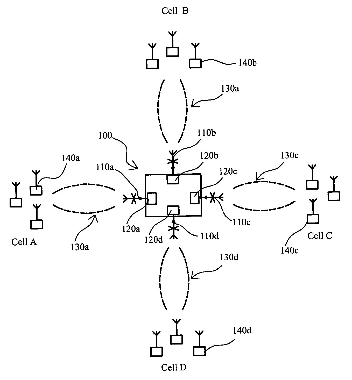
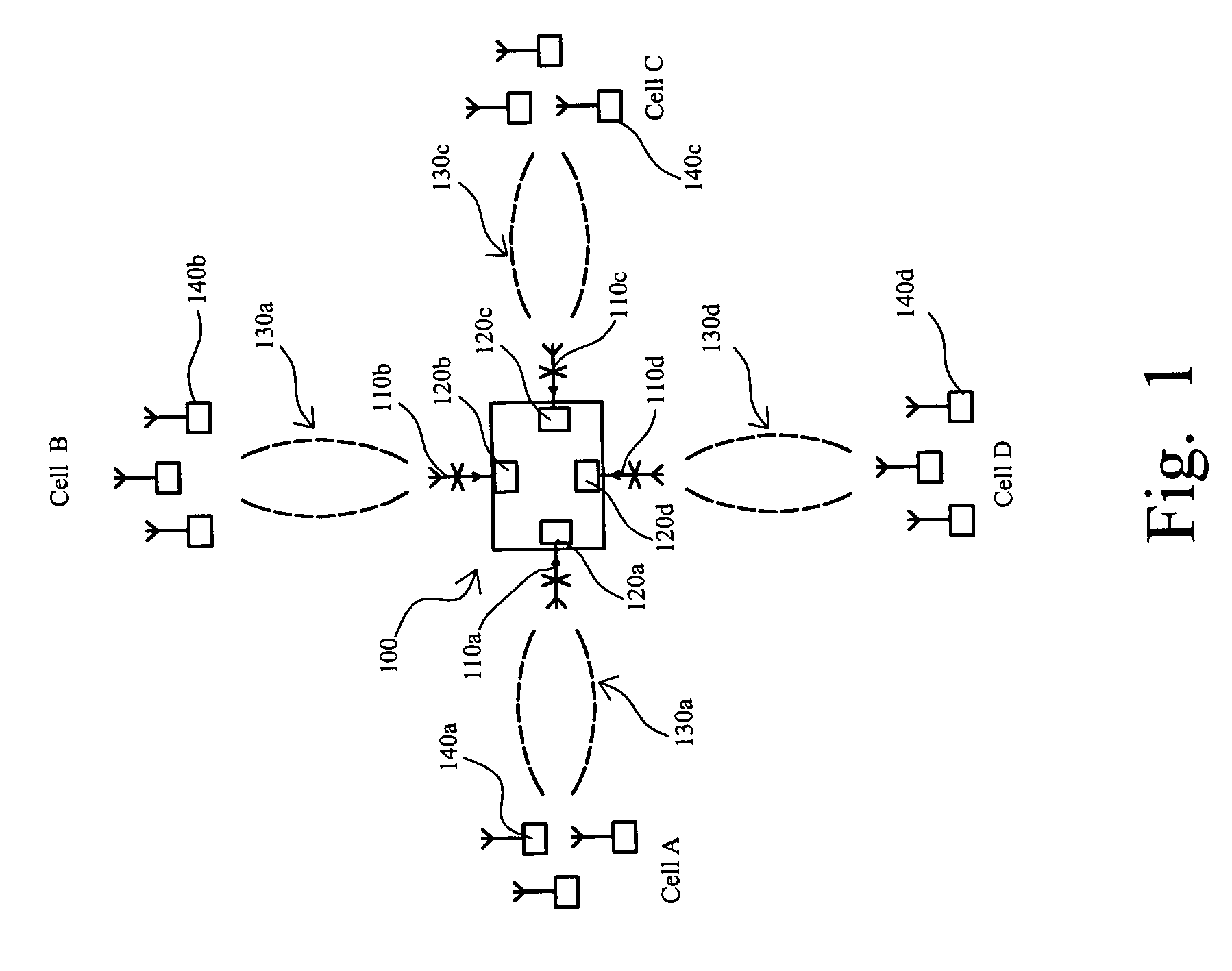
[0018] Referring to FIG. 1, FIG. 1 is a schematic diagram showing the operation of a WLAN device having a smart antenna system, according a preferred embodiment of the present invention. According to the present invention, a WLAN device 100 comprises WLAN transceiver modules 120a-d; and directional antennas 110a-d, wherein the directional antennas 110a-d are installed on the WLAN transceiver modules 120a-d respectively, and are equally spaced apart in the pattern of annular array around the WLAN device 100. Since the radiation patterns 130a-d of the directional antennas 110a-d each is concentrated on one single direction, the directional antennas 110a-d are respectively responsible for the communication among a plurality of users 140a-d in cells A-D. Hence, even if the users 140a-d all use one identical frequency for communication, the communication in the cells A-D will not be mutually interfered, i.e. under the limited bandwidth and space, each of the directional antennas can full...


PUM


Abstract

A WLAN (Wireless Local Area Network) device having a smart antenna system is disclosed for increasing the number of user under a limited bandwidth and a confined environment. The WLAN device having the smart antenna system comprises: a plurality of WLAN transceiver module; and a plurality of directional antennas or array antennas installed on the WLAN transceiver modules by the way of one-to-one, wherein each of the array antennas is composed of a plurality of omni-directional antenna, such as dipole antennas.

Description

FIELD OF THE INVENTION [0001] The present invention relates to a WLAN (Wireless Local Area Network) device having a smart antenna system, and more particularly, to the WLAN device which can increase the number of users under the limited bandwidth and space. BACKGROUND OF THE INVENTION [0002] With the cost of installing a WLAN getting lower and lower, the WLAN receives more welcome from consumers. With respect to hardware, not only desktop computers and notebook computers have owned built-in wireless network function, but also palm computers and tablet PCs have vigorously provided the support for wireless network. Besides, many public locations including airports, cafes and restaurants, etc. have established hot spots of wireless network. [0003] Generally, a WLAN includes several WLAN cards and an access point. The main function of the access point is to connect a wired network and a wireless network, wherein any personal computer installed a wireless network card can share the resou...

Claims


Application Information

Patent Timeline
Patent Type & Authority Applications(United States)
IPC IPC(8): H04L12/28H04W16/28H04W84/12H04W88/08
CPCH04W16/28H04W88/08H04W84/12
Inventor HUNG, PAI-FUYOU, REN-HORNG
Owner ACCTON TECHNOLOGY CORPORATION
Why Eureka
Try Eureka