System and method for using scheduled protocol codes to automatically configure ultrasound imaging systems

a technology of ultrasound imaging system and protocol code, applied in the field of ultrasound imaging system, can solve the problems of prone to errors, prolonging and further slowing down the configuration period of imaging system

Inactive Publication Date: 2005-03-10
KONINKLIJKE PHILIPS ELECTRONICS NV
View PDF28 Cites 28 Cited by
  • Summary
  • Abstract
  • Description
  • Claims
  • Application Information

AI Technical Summary

Problems solved by technology

There are several disadvantages and problems with the above-described technique for configuring ultrasound imaging systems.
First, it requires a substantial period of time for the sonographer to read the chart, determine the protocol code(s) for one or more ultrasound examinations, and then configure the imaging system by manipulating controls or manually entering information and selecting a scanhead that is appropriate for the examination that is to be conducted.
In the event the sonographer has not memorized the configuration parameters for each protocol code, the need to refer to a manual or other document further slows down the configuration of the imaging system.
Second, this technique is prone to errors because it is fairly easy for an sonographer to incorrectly configure the imaging system for the examination that is to be performed, particularly if the sonographer is attempting to rely on memory for the configuration parameters corresponding to a protocol code.
If the imaging system is configured incorrectly, the quality of the examination may very well be compromised.
Although interfacing ultrasound imaging systems to clinical information systems provides significant performance advantages and lessens the possibility of mistakes, it is still less than ideal.
Also, it still requires significant time for the sonographer to properly configure the imaging system, and the sonographer may configure the imaging system incorrectly or less than optimum for the procedure that is to be performed.
Although the monitor described by Schraag et al. does facilitate the entry of information in to the monitor, the entered information does not automatically set up the monitor for any specific purpose nor does it tag the test results with information identifying the patient.
As a result, the use of the Schraag et al. monitor is still time-consuming and prone to error.

Method used


Image

  • System and method for using scheduled protocol codes to automatically configure ultrasound imaging systems
  • System and method for using scheduled protocol codes to automatically configure ultrasound imaging systems
  • System and method for using scheduled protocol codes to automatically configure ultrasound imaging systems

Examples


Embodiment Construction

[0015] Embodiments of the present invention are directed to ultrasound imaging systems. Certain details are set forth below to provide a sufficient understanding of various embodiments of the invention. However, it will be clear to one skilled in the art that the invention may be practiced without these particular details. In other instances, well-known circuits, control signals, and timing protocols have not been shown in detail in order to avoid unnecessarily obscuring the invention.

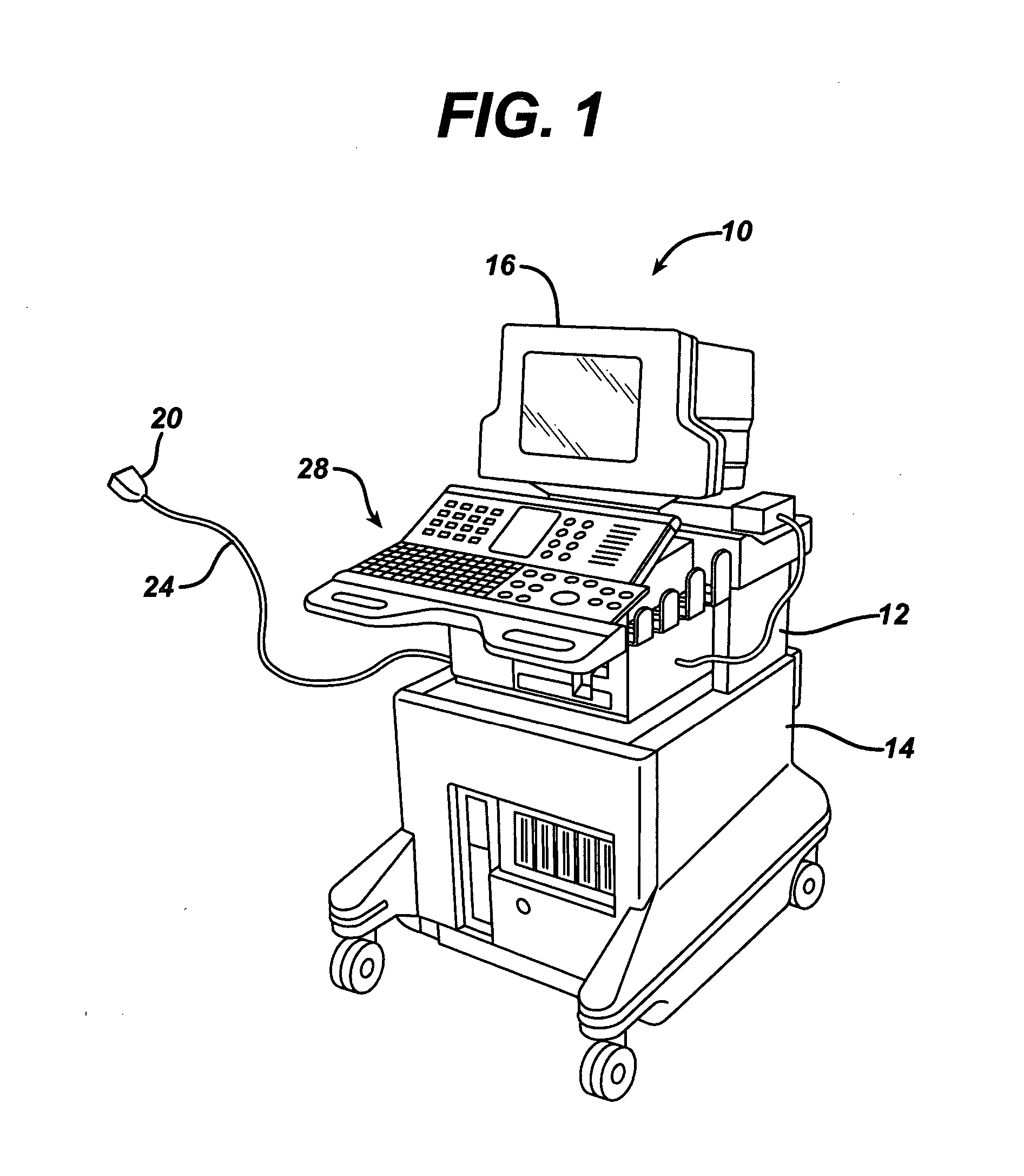
[0016] An ultrasound imaging system 10 in accordance with one embodiment of the invention is illustrated FIG. 1. The system 10 includes a chassis 12 containing most of the electronic circuitry for the system 10. The chassis 12 is mounted on a cart 14, and a display 16 is mounted on the chassis 12. An ultrasound imaging probe 20 is connected to the chassis 14 by a cable 24. Different imaging probes 20 are generally used for different types of ultrasound examinations. The chassis 12 includes a keyboard ...


PUM


Abstract

An ultrasound imaging system (10) allows the entry of protocol codes that correspond to respective ultrasound examinations, and then uses the protocol codes to automatically configure the imaging system (10) for the corresponding examination. The imaging system (10) uses the protocol codes to select all of the operating parameters for the imaging system (10), to prompt a sonographer using the imaging system (10) to attach the appropriate ultrasound probe (20), and to determine the content and format of a display (16) that is presented or a report that is generated at the conclusion of the examination.

Description

[0001] This invention claims the benefit of Provisional U.S. Patent Application Ser. No. 60 / 501,852, filed Sep. 10, 2003.TECHNICAL FIELD [0002] This invention relates to ultrasound imaging systems, and, more particularly, to a system and method facilitating the setup of ultrasound imaging systems based on the type of ultrasound examination that is to be performed. BACKGROUND OF THE INVENTION [0003] Ultrasound imaging systems are widely used to obtain a variety of ultrasound images. Ultrasound imaging systems may be used to scan different parts of the body and the same parts of the body using different techniques or imaging modalities. For example, the arm of a patient may be scanned by placing an ultrasound transducer against different surfaces of the arm to obtain images from different directions. Further, each image may be obtained by either keeping the ultrasound transducer stationery or scanning the transducer across the surface of the skin while the image is being obtained. To ...

Claims


Application Information

Patent Timeline
Patent Type & Authority Applications(United States)
IPC IPC(8): A61B8/00
CPCA61B8/00A61B8/467A61B8/4405A61B8/461A61B8/585
Inventor LOVE, SCOTT
Owner KONINKLIJKE PHILIPS ELECTRONICS NV
Why Eureka
Try Eureka