
FTTH system for convergence of broadcasting and communication through switched broadcasting

a technology of switched broadcasting and fiber optics, applied in the field of fiber optics to the home network for convergence of broadcasting and communication, can solve the problems of increasing the cost of the entire system, limiting the number of onts that can be in communication with one olt, and expensive optical amplifiers, and achieves the effect of increasing the transmission speed

Inactive Publication Date: 2005-03-10
SAMSUNG ELECTRONICS CO LTD
View PDF3 Cites 36 Cited by
  • Summary
  • Abstract
  • Description
  • Claims
  • Application Information

AI Technical Summary

Benefits of technology

[0019] A second object of the present invention is to provide a FTTH network for the convergence of broadcasting and communications, in which an ONU performs switching for broadcasting and transmits only broadcasting information switched to each subscriber, so that a bandwidth can be efficiently used.
[0021] A fourth object of the present invention is to provide a FTTH network for convergence of broadcasting and communication which enables a low priced light source operating at a low speed to be used, without using an expensive light source for increasing a transmission speed, because digital broadcastings in all channels are not transmitted to each of the subscribers.

Problems solved by technology

Firstly, the PON structure, in which one OLT transmits a signal to the N number of ONTs by means of the power splitting method, has a limitation in the number of the ONTs that can be in communication with the one OLT.
Accordingly, when the number of the ONTs exceeds 64, since another PON system is additionally required as the maximum of the first PON has been exceeded, then the overlay operation must be performed by means of another analog optical transmitter, increasing the costs of the entire system.
Further, when 64 divisions at maximum are performed, an expensive optical amplifier, such as an EDFA, must be used next to the optical transmitter in order to increase the intensity of an optical signal and secure a carrier to noise ratio (CNR) for maintaining broadcasting quality.
Furthermore, even in a case of a network utilizing an optical transmitter and the optical receiver, an expensive optical transceiver having a good property is required, increasing these costs of the entire system increases.

Method used


Image

  • FTTH system for convergence of broadcasting and communication through switched broadcasting
  • FTTH system for convergence of broadcasting and communication through switched broadcasting
  • FTTH system for convergence of broadcasting and communication through switched broadcasting

Examples


Embodiment Construction

[0029] Hereinafter, preferred aspects of the present invention will be described with reference to the accompanying drawings. The same reference numerals are used to designate the same elements as those shown in other drawings. In the following description of the present invention, a detailed description of known functions and configurations incorporated herein will be omitted when it may obscure the subject matter of the present invention.

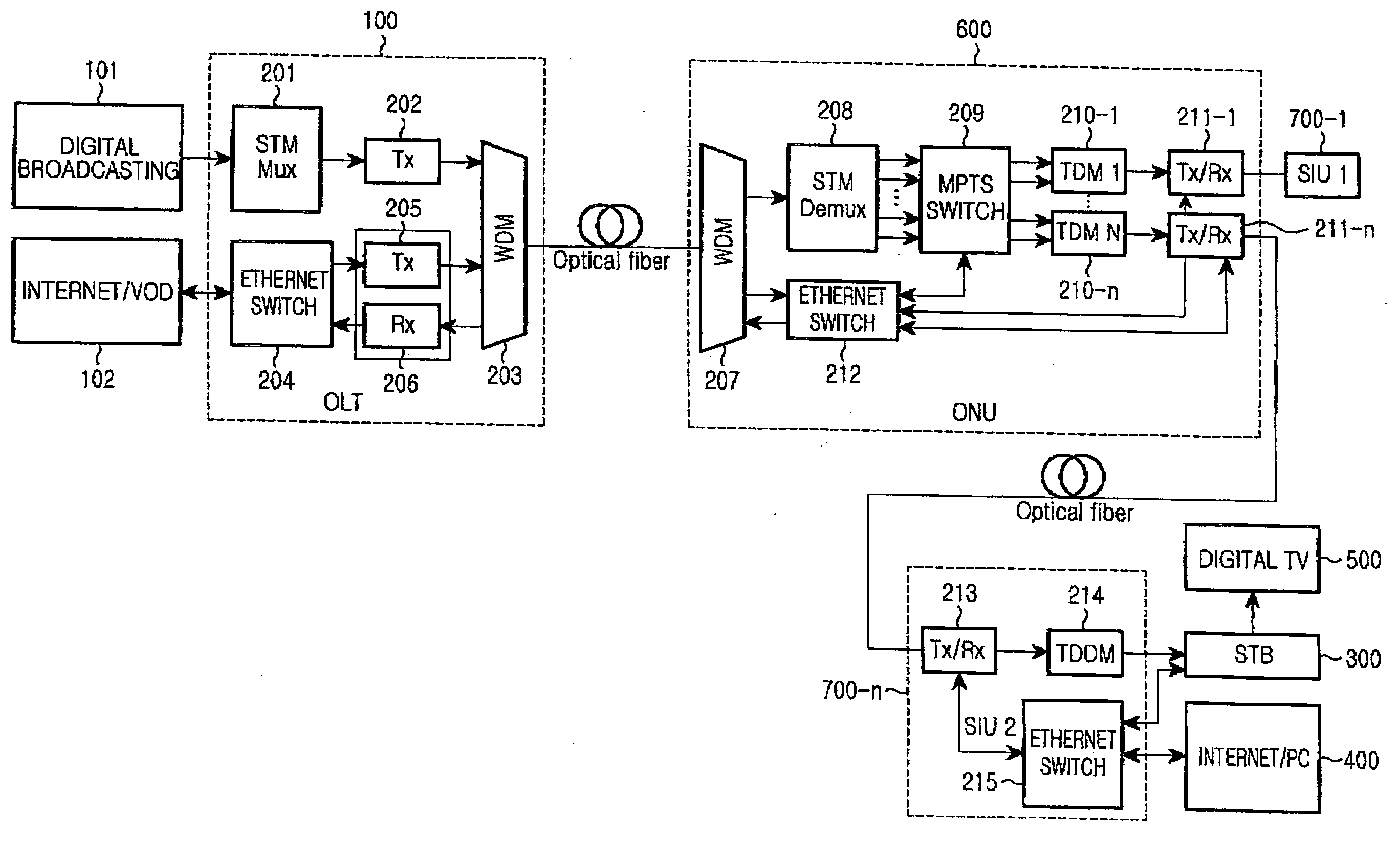
[0030]FIG. 2 is a block diagram showing an FTTH network for convergence of broadcasting and communication through a switched broadcasting according to a first aspect of the present invention.

[0031] As shown in FIG. 2, an OLT 100 and an ONU 600 are connected to each other through one optical fiber, and a downstream output of the ONU 600 is connected to each subscriber interface unit (hereinafter, referred to as an SIU) 700-1 or 700-n through respective optical fibers, so that a true FTTH network is formed.

[0032] According to the present inventio...


PUM


Abstract

A fiber to the home FTTH network for convergence of broadcasting and communication is disclosed. The network includes: an OLT for receiving and converting a first predetermined number of broadcast signals and an Ethernet signal into a plurality of converted optical signals, combining the converted optical signals into converged optical signals for subsequent transmission by an optical wavelength division multiplexing method; and an optical network unit (ONU) for classifying the optical signal transmitted from the OLT into the first predetermined number of broadcast signals and the Ethernet signal, switching a second predetermined number of broadcasting signals of the first predetermined number of broadcasting signals according to each SIU by channel selection information contained in upstream Ethernet information, and switching the Ethernet signal to be transmitted to the SIU according to each SIU so as to transmit the switched signal.

Description

CLAIM OF PRIORITY [0001] This application claims priority to an application entitled “FTTH system for convergence of broadcasting and communication through switched broadcasting” filed in the Korean Intellectual Property Office on Sep. 8, 2003 and assigned Serial No. 2003-62856, the contents of which are hereby incorporated by reference. BACKGROUND OF THE INVENTION [0002] 1. Field of the Invention [0003] The present invention relates to a Fiber-To-The-Home (FTTH) network for convergence of broadcasting and communication. [0004] 2. Description of the Related Art [0005] In the prior art, in order to provide for the efficient exchange of an Ethernet signal which is a communication signal, a passive optical network (hereinafter, referred to as a PON) structure. In such a network, there is generally one optical line terminal (hereinafter, referred to as an OLT) that is located at a telephone office. The OLT is subsequently connected to an N number of optical network terminals (hereinafte...

Claims


Application Information

Patent Timeline
Patent Type & Authority Applications(United States)
IPC IPC(8): H04B10/272H04B10/524H04B10/556H04H1/00H04L12/44H04H20/69H04J14/02H04L12/28H04N7/173H04N7/22H04Q11/00
CPCH04H20/69H04J14/0226H04J14/0279H04J14/0282H04L12/2801H04N7/17309H04J14/0252H04Q11/0066H04Q11/0067H04Q11/0071H04J14/0232H04J14/0247H04N7/22H04B10/25H04B10/2581
Inventor JOO, YOUNG-HUNKOH, JUN-HOKIM, CHAN-YULCHO, JAE-HUN
Owner SAMSUNG ELECTRONICS CO LTD
Learn More