
Compliant buoyancy can guide

a technology of buoyancy guide and compliant, which is applied in the direction of special purpose vessels, vessel construction, and borehole/well accessories, etc., can solve the problems of insufficient account, difficult practical design of strength and fatigue, and different nature of signals, etc., to reduce stick-slip fatigue, less stiffness, and cost-effective

Inactive Publication Date: 2005-03-10
TECH FRANCE SA
View PDF20 Cites 1 Cited by
  • Summary
  • Abstract
  • Description
  • Claims
  • Application Information

AI Technical Summary

Benefits of technology

[0009] According to one exemplary embodiment of the invention, a guide for a buoyancy can on a floating offshore platform is provided. The platform includes at least one support structure adjacent the buoyancy can. The guide comprises at least one compliant guide member supported by the support structure adjacent the exterior surface of the buoyancy can. Lateral movement of the buoyancy can toward the support structure compresses the compliant member so as to absorb the force generated by the buoyancy can movement, and so as to protect the buoyancy can and components of the floating offshore platform from damage. A wear pad disposed between each guide structure and the buoyancy can protects the guide and buoyancy can from friction wear.
[0010] According to another exemplary embodiment of the invention, the support structure has at least one projection attached thereto. A buoyancy can guide is provided that comprises at least one elastomeric compression pad supported by the support structure and adjacent the exterior surface of the buoyancy can. Lateral movement of the buoyancy can toward the support structure compresses the elastomeric compression pad so as to absorb the force generated by the buoyancy can movement, and so as to protect the buoyancy can and components of the floating offshore platform from damage. A wear pad disposed between each elastomeric compression pad and the buoyancy can protects the compression pad from friction wear against the buoyancy can. At least one carriage is attached to the guide. The carriage has a channel therein that slidingly engages the projection on the support structure.
[0011] According to still another exemplary embodiment of the invention, the support structure has upper and lower projections attached thereto. A buoyancy can guide is provided that comprises a plurality of elastomeric compression pads supported by the support structure and adjacent the exterior surface of the buoyancy can. Each compression pad has first and second opposite sides. Lateral movement of the buoyancy can toward the support structure compresses the elastomeric compression pads so as to absorb the force generated by the buoyancy can movement, and so as to protect the buoyancy can and components of the floating offshore platform from damage. A first rigid plate is associated with the first side of the compression pad. A second rigid plate is disposed between and affixed to the support structure and the second side of the compression pad for affixing the compression pad to the support structure. A wear pad support is attached to the first rigid plate. The wear pad support has upper and lower ends and comprises a base plate, a pair of spaced side plates attached to and extending from the base plate, and a top plate extending between the side plates. A wear pad is secured to the wear pad support. The wear pad is disposed between the compression pad and the buoyancy can for protecting the compression pad and buoyancy can from friction wear. Upper and lower carriages extend from the upper and lower ends, respectively, of the wear pad support. Each carriage has a channel therein that slidingly engages a respective projection on the support structure.
[0012] According to yet another exemplary embodiment of the invention, the support structure has upper and lower projections attached thereto. A buoyancy can guide is provided that comprises a plurality of elastomeric compression pads supported by the support structure and adjacent the exterior surface of the buoyancy can. Each compression pad has first and second opposite sides. Lateral movement of the buoyancy can toward the support structure compresses the elastomeric compression pads so as to absorb the force generated by the buoyancy can movement, and so as to protect the buoyancy can and components of the floating offshore platform from damage. A bearing plate is affixed to the first side of the compression pad. A first rigid plate is affixed to the bearing plate. A second rigid plate is disposed between and affixed to the support structure and the second side of the compression pad for affixing the compression pad to the support structure. A wear pad support is attached to the first rigid plate. The wear pad support has upper and lower ends. The wear pad support comprises a base plate, a pair of spaced side plates attached to and extending from the base plate, and a top plate extending between the side plates. A wear pad is secured to the wear pad support. It is disposed between the compression pad and the buoyancy can for protecting the compression pad and buoyancy can from friction wear. Upper and lower carriages extend from the upper and lower ends, respectively, of the wear pad support. Each carriage has a channel therein that slidingly engages a respective projection on the support structure.
[0013] In one particular preferred embodiment, the compliant buoyancy can guide comprises a pair of nested elastomeric compression pads, that is, a first compression pad circumferentially surrounding a second compression pad. The first elastomeric compression pad is more compliant (i.e., less stiff) than the second pad, so that a non-linear load deflection response is achieved in a compact and cost-effective structure. For relatively small deflections, the compliant can guide of this design provides small loads, a result that is essential during the installation process, and that reduces stick-slip fatigue on the risers supported by the buoyancy cans. For relatively large deflections, this embodiment provides higher loads that reduce the fatigue loads on the buoyancy can and the platform.
[0014] According to still another exemplary embodiment of the invention, apparatus for compliantly guiding a buoyancy can on a floating offshore platform is provided. The apparatus comprises a plurality of spaced support structures attached to the platform and arranged radially around the exterior circumferential surface of the buoyancy can. At least one elastomeric compression pad is attached to each support structure and disposed adjacent the exterior surface of the buoyancy can. Lateral movement of the buoyancy can toward one of the support structures compresses the elastomeric compression pad attached thereto so as to absorb the force generated by the buoyancy can movement, and so as to protect the buoyancy can and components of the floating offshore platform from damage.

Problems solved by technology

Recent analytical and model test work has indicated that the conclusions made previously did not fully account for impact loads, and that the nature of the signal is quite different if there is a gap that is large enough for these fabrication tolerances.
Loads on the buoyancy can and guide have been found to be large and numerous enough to make practical design for both strength and fatigue difficult.
However, in alternative embodiments, there is zero preload, since introduction of an unnecessarily high preload could potentially introduce other problems.

Method used


Image

  • Compliant buoyancy can guide
  • Compliant buoyancy can guide
  • Compliant buoyancy can guide

Examples


Embodiment Construction

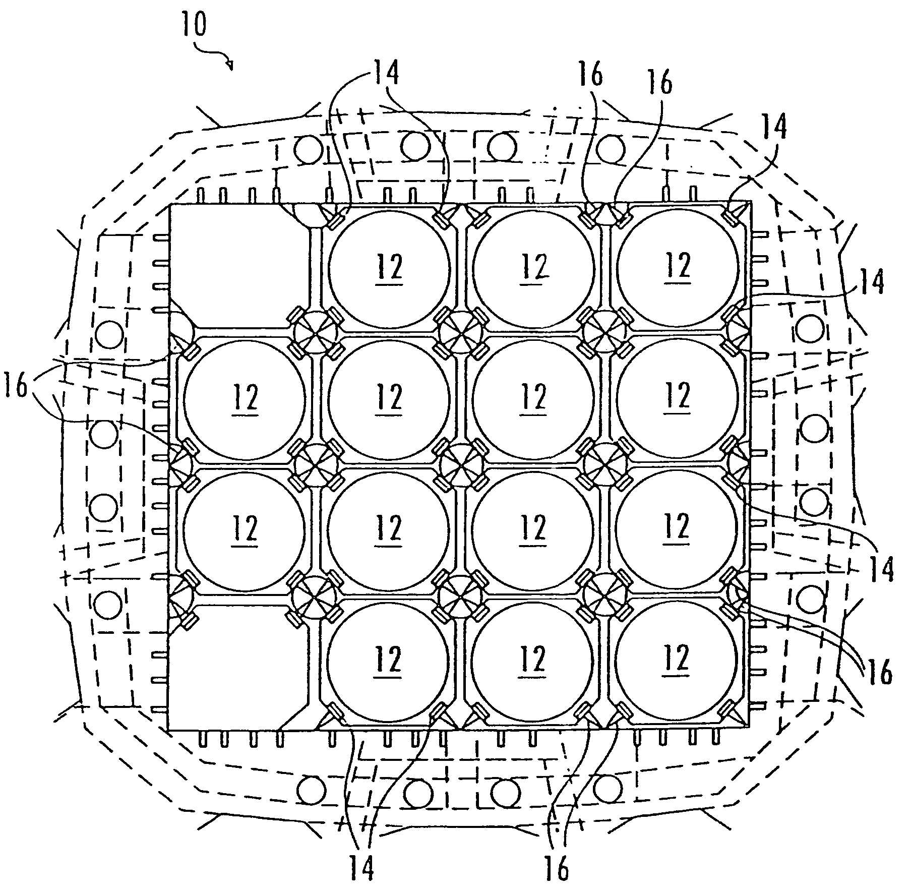
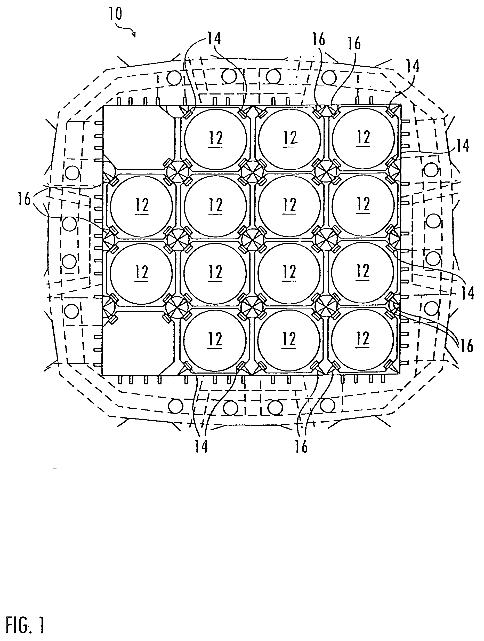
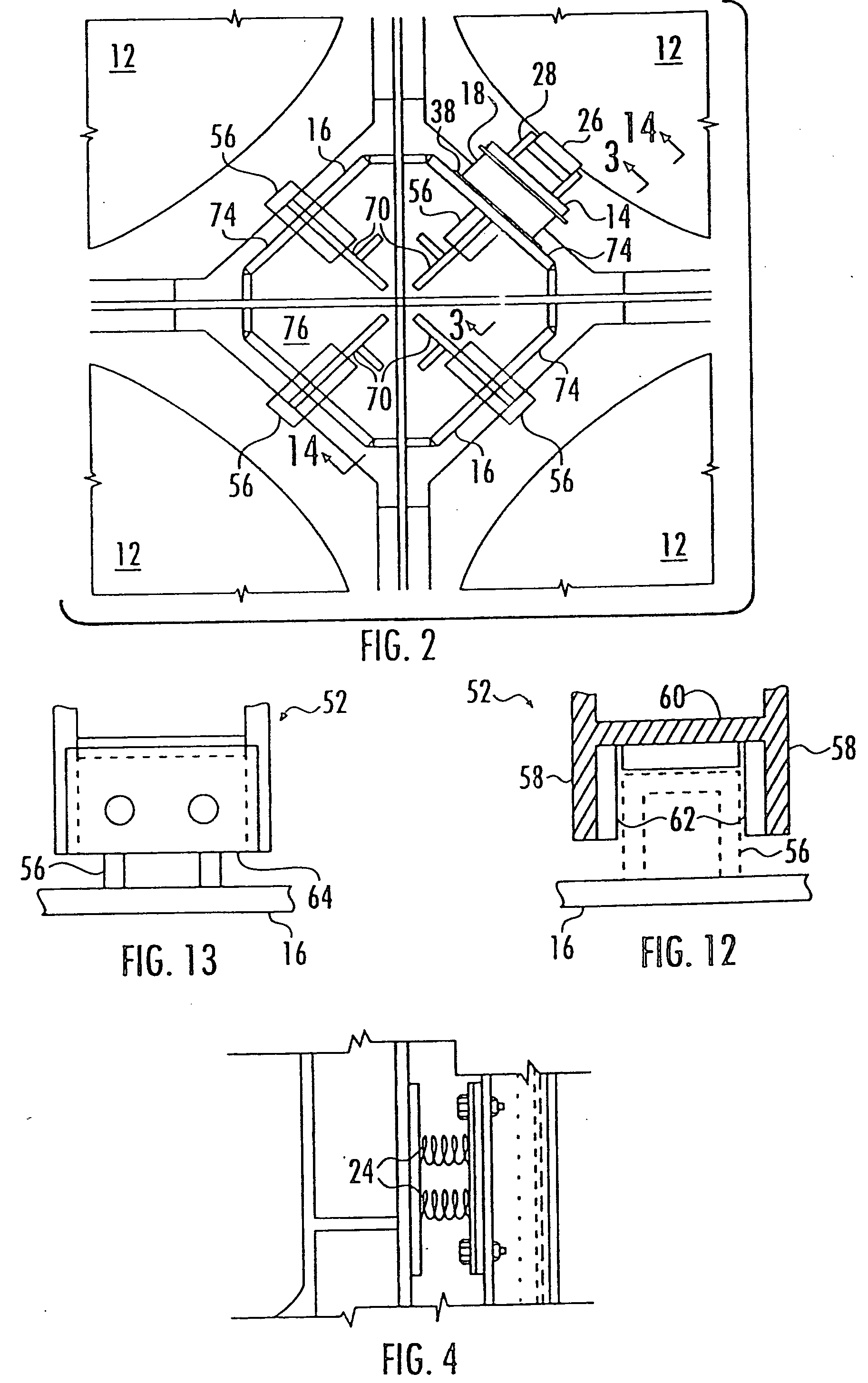
[0046] In FIG. 1, there is shown, in a lateral cross-sectional view, a spar-type floating offshore mineral exploration and production platform, generally designated 10. In this example, the platform 10 includes a plurality of cylindrical buoyancy cans 12. A plurality of compliant guides 14 are spaced around the exterior circumferential surface of each buoyancy can 12. Although FIG. 1 shows four compliant guides 14 for each buoyancy can 12, it will be understood that more or fewer guides 14 may be used. The platform 10 in the present example also includes a plurality of support structures 16 to which the compliant guides 14 are attached. Examples of buoyancy cans 12, compliant guides 14, and support structures 16 are more clearly seen in FIG. 2, and will be more fully described below.

[0047] Referring now to FIG. 3, the illustrated exemplary compliant guide 14 includes three vertically spaced elastomeric compression pads 18, 20, and 22. Lateral movement of the buoyancy can 12 (not sh...


PUM


Abstract

A floating offshore platform, of the type having a buoyancy can disposed within a support structure, includes a can guide assembly that has at least two compliant compression pads that are configured and arranged to provide a non-linear load-versus-deflection characteristic in response to impact loads generated by the impact of the can against the guide assembly. At least one of the compression pads is substantially stiffer (less compliant) than the other pad. The pads are arranged so that the relatively soft pad absorbs the impact load before the relatively stiff pad is engaged. In one embodiment, first, second, and third compression pads are arranged vertically, the upper and lower pads being softer (more compliant) than the middle pad. In another embodiment, a first, relatively soft, compression pad coaxially surrounds a second, relatively stiff compression pad.

Description

CROSS-REFERENCE TO RELATED APPLICATIONS [0001] This application is a continuation-in-part of co-pending application Ser. No. 09 / 850,599; filed May 7, 2001, the disclosure of which is incorporated herein by reference, which, in turn, claims the benefit, under 35 U.S.C. Section 119(e), of provisional application No. 60 / 283,240; filed Apr. 11, 2001, the disclosure of which is likewise incorporated herein by reference.FEDERALLY SPONSORED RESEARCH OR DEVELOPMENT [0002] Not applicable BACKGROUND OF THE INVENTION [0003] The present invention generally relates to floating offshore mineral exploration and production platforms and, more particularly, is concerned with a compliant guide for protecting the buoyancy cans and components of the floating offshore platform from damage from impacts that may occur as a result of hydrodynamic loads (e.g. Froude-Krylov impact forces) on the buoyancy cans. [0004] The spacing between the buoyancy can outer wall and the contact point of the guide structure...

Claims


Application Information

Patent Timeline
Patent Type & Authority Applications(United States)
IPC IPC(8): B63B35/44B63B35/613B63B59/02
CPCB63B35/4413B63B59/02B63B35/613
Inventor KARAYAKA, METINMONTAGUE, JOHN
Owner TECH FRANCE SA
Learn More