
Analysis system

a technology of analysis system and analysis method, applied in the field of analysis system, can solve problems such as the condition of the machine to deteriora

Inactive Publication Date: 2005-03-03
SPM INSTR
View PDF70 Cites 36 Cited by
  • Summary
  • Abstract
  • Description
  • Claims
  • Application Information

AI Technical Summary

Benefits of technology

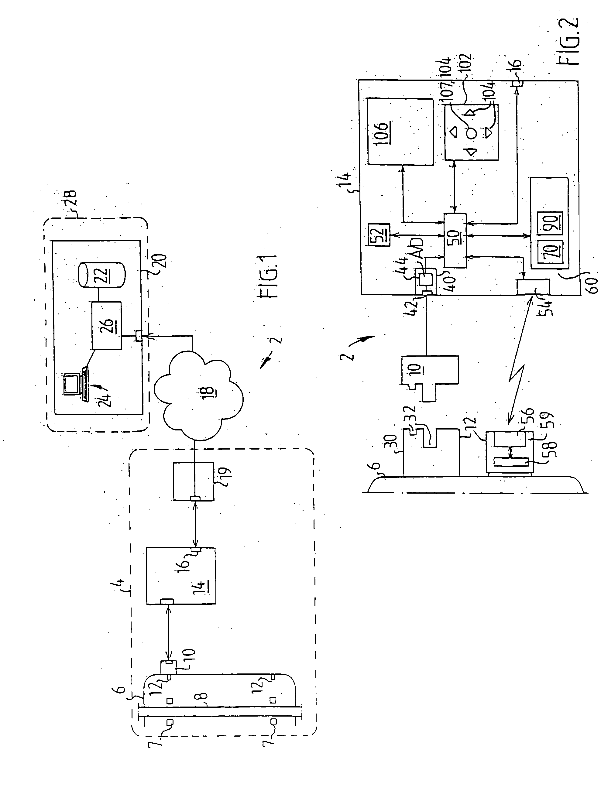
The invention relates to an apparatus for analyzing the condition of a machine by using a sensor to measure vibrations at a specific point on the machine. The apparatus includes a data processing system that performs various condition monitoring functions, such as detecting changes in the machine's condition. The apparatus can be used at a reduced cost for the supplier while still maintaining profitability for the supplier. The invention also provides an improved method for detecting changes in machine condition by using a sensor attached to the machine and a communications means for analyzing the data collected from the sensor.

Problems solved by technology

Machines with moving parts are subject to wear with the passage of time, which often causes the condition of the machine to deteriorate.

Method used


Image

  • Analysis system
  • Analysis system
  • Analysis system

Examples


example 1

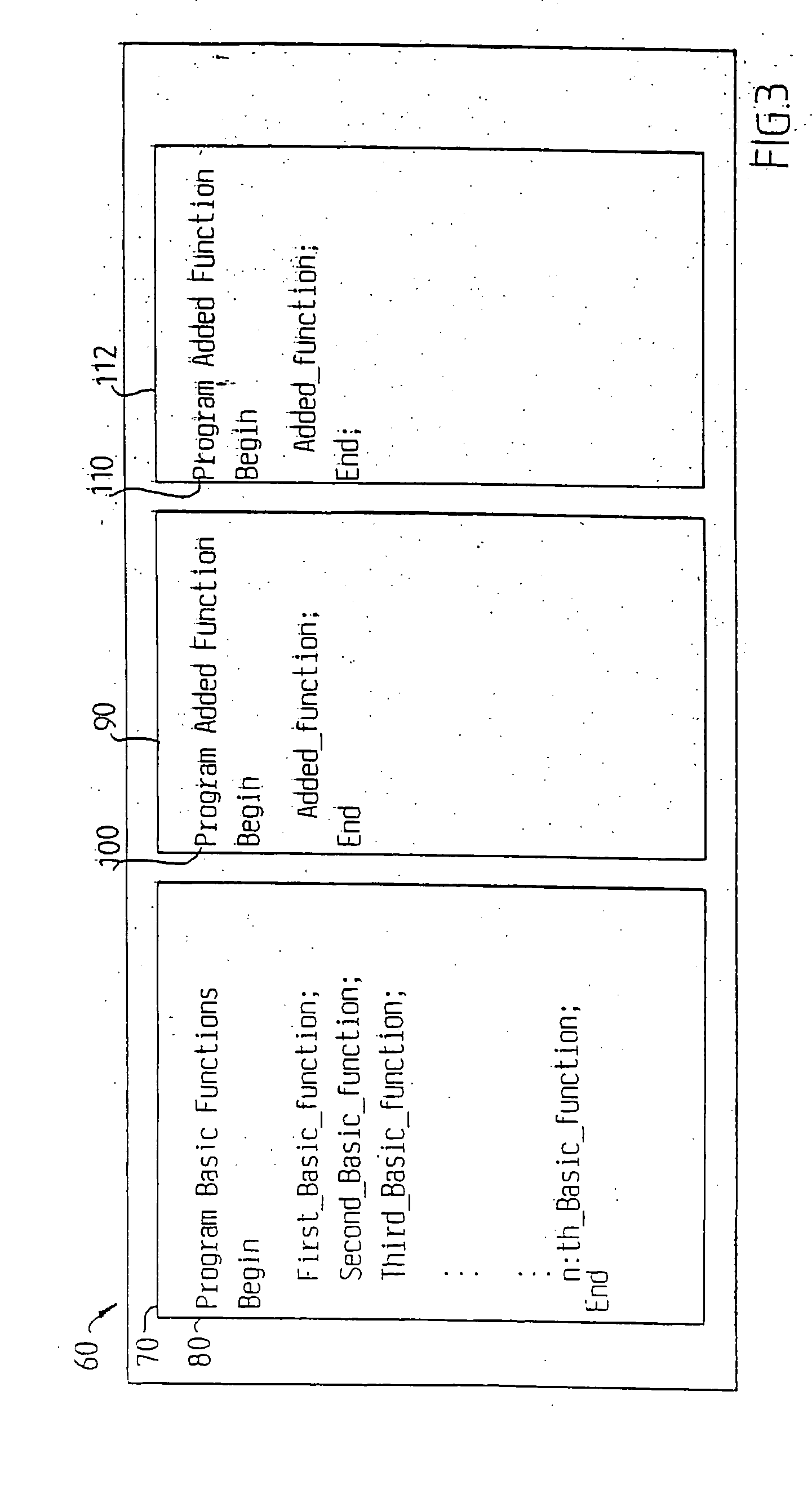
FIG. 5C is a simplified illustration of a principle of an embodiment of an account value or amount of usage parameter for use in an apparatus wherein a user pays to get a number of credits, also referred to as “units of use”. It is noted that in the Example 1 embodiment the computer program routine “Function_F1” becomes disabled when the parameter Use_F1 reaches a first reference value (zero in the example).

This example describes an embodiment relating to the above-mentioned procedure. When a client has purchased e.g. ten units of use for the computer program routine “Function_F1” (See FIG. 4), the amount indication portion of the key may cause the parameter Use_F1 to increase by ten units. Hence, if the parameter Use_F1 had a numerical value zero (0) before reception of the key, then the parameter Use_F1 will have numerical value “10” (ten) after correct reception of that key. For each execution of the computer program routine “Function_F1” the numerical value of the parameter Us...

example 2

This example describes an embodiment similar to the Example 1 embodiment above. According to example 2, the cost per use changes after a certain level of use has been attained. A user can enter a number Ap of credits or units of use for a selected function, such as function F1, by means of entering a key. When the function F1 is executed by the apparatus 14 the use of the condition monitoring function F1 will be registered by deducting e.g. one credit for each execution. However, the method may also include the steps of: reading a current value of said registered use; comparing said current value with a second reference value; registering use at a first rate when said current value is above the second reference value; and registering use at a second rate when said current value is below the second reference value.

This advantageously enables a supplier to sell usage at different costs. When, according to one embodiment, a user has paid for a certain amount Ap of usage, the sec...


PUM


Abstract

An apparatus for analysing the condition of a machine, comprising: at least one input for receiving measurement data from a sensor for surveying a measuring point of the machine; data processing means for processing condition data dependent on said measurement data; said data processing means comprising means for performing a plurality of condition monitoring functions (F1, F2,Fn); and a logger for registering use of at least one of said condition monitoring functions (F1, F2,Fn).

Description

TECHNICAL FIELD OF THE INVENTION The present invention relates to an apparatus for analysing the condition of a machine, and to a system for analysing the condition of a machine. The invention also relates to method of operating such a system. DESCRIPTION OF RELATED ART Machines with moving parts are subject to wear with the passage of time, which often causes the condition of the machine to deteriorate. Examples of such machines with movable parts are motors, pumps, generators, compressors, lathes and CNC-machines. The movable parts may comprise a shaft and bearings. In order to prevent machine failure, such machines should be subject to maintenance, depending on the condition of the machine. Therefore the operating condition of such a machine is preferably evaluated from time to time. The operating condition can be determined by measuring vibrations emanating from a bearing or by measuring temperature on the casing of the machine, which temperatures are dependent on the operati...

Claims


Application Information

Patent Timeline
Patent Type & Authority Applications(United States)
IPC IPC(8): G01D18/00G01H1/00G01M15/04G01M15/12G07C3/00G07C3/08G07C3/10G07C9/00
CPCG01D18/008G01H1/003G01M13/045G01M15/04G07C9/00142G07C3/00G07C3/08G07C3/10G07C9/00103G01M15/12G07C9/27G07C9/33
Inventor LINDBERG, STEFANHEDLUND, HAKANKUMMELSTAM, JIMLINDBERG, JARL-OVE
Owner SPM INSTR
Learn More