
Image processing device, image processing method and image processing program

a technology of image processing and image processing method, applied in the field of error diffusion, can solve the problems of long processing time required for error diffusion, unevenness on the output image, and affecting the quality of the output image, so as to shorten the processing time, and prevent the development of moiré or unevenness

Inactive Publication Date: 2005-03-03
BROTHER KOGYO KK
View PDF4 Cites 7 Cited by
  • Summary
  • Abstract
  • Description
  • Claims
  • Application Information

AI Technical Summary

Benefits of technology

[0011] The invention provides a technique to reduce the tendency to cause moiré and unevenness on the output image.
[0020] The image processing program of the invention is configured to operate the computer as the plurality of setting devices. The setting device, which is selected from the plurality of the setting devices, is allowed to set a threshold value. Accordingly, for example, a threshold value which is a low value and set by the first setting device allows the dots to be uniformly diffused, and a threshold value which is a high value and set by the second setting device prevents the development of a moiré. Thus, a small-sized error distribution matrix is used and a processing time is shortened. In addition, the development of the moiré and unevenness can be prevented. The image processing program may be stored in a computer-readable recording medium, for example, a CD-ROM and a floppy disk.

Problems solved by technology

However, when an image having low and uniform density is processed, the above error diffusion is likely to cause moiré on the output image because dots are regularly generated and placed in the output image.
However, because the large-sized error distribution matrix is so large, a long processing time is required for the error diffusion.
However, with the such error diffusion, unevenness is developed on the output image due to the random dot placement.

Method used


Image

  • Image processing device, image processing method and image processing program
  • Image processing device, image processing method and image processing program
  • Image processing device, image processing method and image processing program

Examples


first embodiment

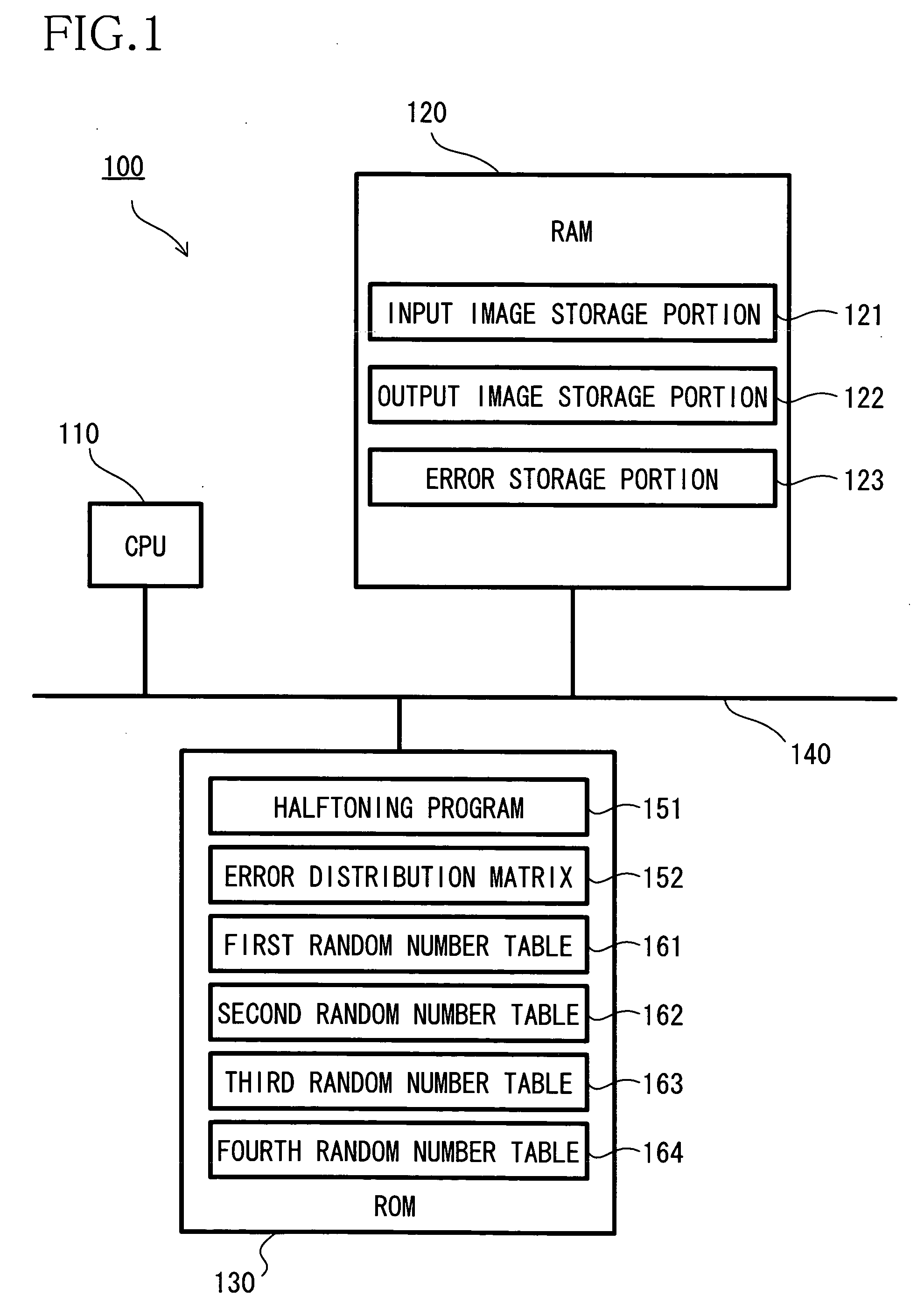
[0079] In the printer 100 of the first embodiment, the processes of S137, S139 and S141 of the threshold value determination process (FIG. 5) function as a setting device. Particularly, the process of S137 functions as a first setting device, and the processes of S139 and S141 function as a second setting device. The processes of S131 to S136 function as a threshold value selecting device. The process of S138 functions as a random number generator selecting device. Each random number table 161 to 164 functions as a random number generator.

[0080] As described above, in the printer 100 of the first embodiment, by the threshold value determination process, the low threshold value T (T=2) is selected with high probability and the high threshold value T (T=a random number in the range of 64 to 192) is selected with low probability. Therefore, according to the printer 100 of the embodiment, when the binarization is performed on the input image having low and uniform density, the moiré and...

second embodiment

[0105] Next, a threshold value determination process of the second embodiment will be described with reference to FIG. 15. When the threshold value determination process starts, at S231, the value of the random number, which exists at the reference position indicated by the variable n1 in the first random number table 161, is substituted into the variable T1. Then, at S232, one (1) is added to the value of the variable n1.

[0106] At S233, it is determined whether the value of the variable T1 is greater than 224. When the value of the variable T1 is greater than 224 (S233:YES), flow moves to S234. At S234, the value of the random number, which exists at the reference position indicated by the variable n3 in the third random number table 163, is determined as the threshold value T. Then, at S235, one (1) is added to the value of the variable n3. The threshold value determination process is finished.

[0107] When the value of the variable T1 is not greater than 224 (i.e., the value of th...


PUM


Abstract

An image processing device performs an error diffusion on multilevel input image data to generate multilevel output image data that has fewer levels than the multilevel input image data. The image processing device includes a plurality of setting devices, each of which sets a threshold value to be used at the error diffusion, a threshold value selecting device that randomly selects one of the plurality of setting devices with respect to each pixel to be processed and allows the selected setting device to set a threshold value with respect to the pixel to be processed when the image processing device performs the error diffusion, and a converting device that converts the pixel to be processed into multilevel output image data with fewer levels than multilevel input image data by the error diffusion, in accordance with the threshold value set by the setting device selected by the threshold value selecting device. The plurality of setting devices includes at least a first setting device and a second setting device that sets a threshold value which is higher than a threshold value set by the first setting device.

Description

[0001] This application claims priority from JP 2003-307230, filed Aug. 29, 2003, the subject matter of which is incorporated herein in its entirety by reference thereto. BACKGROUND OF THE INVENTION [0002] 1. Field of Invention [0003] The invention relates to an error diffusion that generates multilevel output image data having fewer levels than multilevel input image data. [0004] 2. Description of Related Art [0005] Conventionally, the error diffusion is known as a technique to generate multilevel output image data (e.g. bi-level output image data) from multilevel input image data, wherein the output image data has fewer levels than the input image data. The error diffusion of binarizing 256 levels input image data will be briefly described below. [0006] First, a density I of a pixel to be processed (a subject pixel) of input image data is modified to obtain a modified density I′, with the addition of binary conversion errors e distributed to pixels located in a neighborhood of the...

Claims


Application Information

Patent Timeline
Patent Type & Authority Applications(United States)
IPC IPC(8): B41J2/52G06T1/00G06T5/00H04N1/405H04N1/407H04N1/52H04N1/60
CPCH04N1/4053
Inventor YOSHIDA, YASUNARI
Owner BROTHER KOGYO KK
Learn More