
Secure activation of a downhole device

a technology of secure activation and downhole device, which is applied in the direction of survey, lighting and heating apparatus, and wellbore/well accessories, etc., can solve the problems of inadvertent activation of certain types of explosive devices, limiting the communication options available to well operators, and creating safety concerns when activating downhole tools. , to achieve the effect of more secure communication

Inactive Publication Date: 2005-03-03
SCHLUMBERGER TECH CORP
View PDF72 Cites 73 Cited by
  • Summary
  • Abstract
  • Description
  • Claims
  • Application Information

AI Technical Summary

Benefits of technology

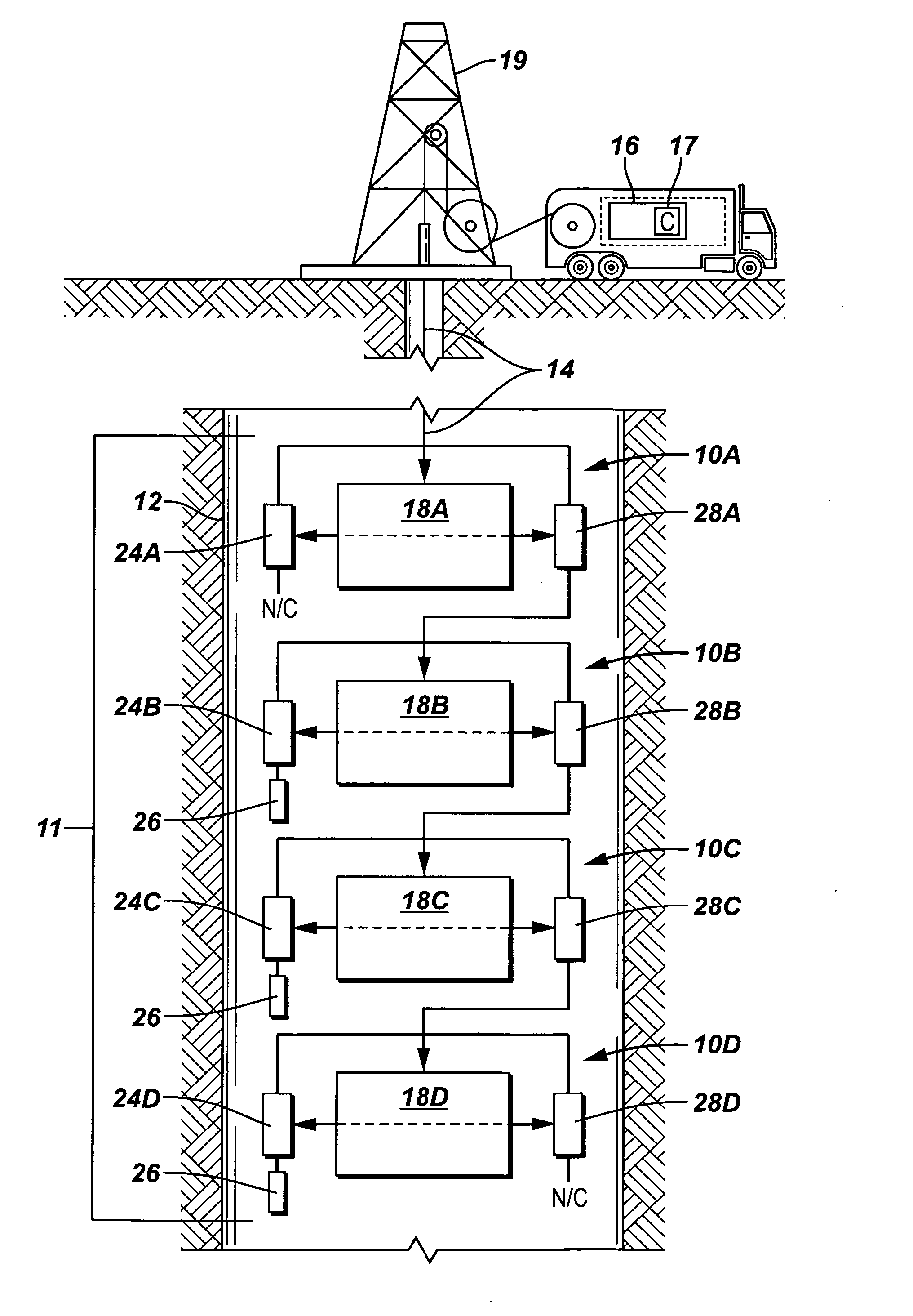
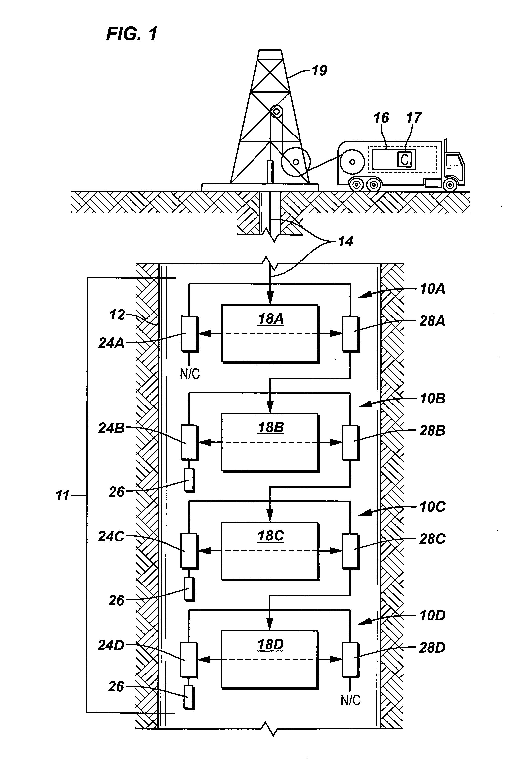
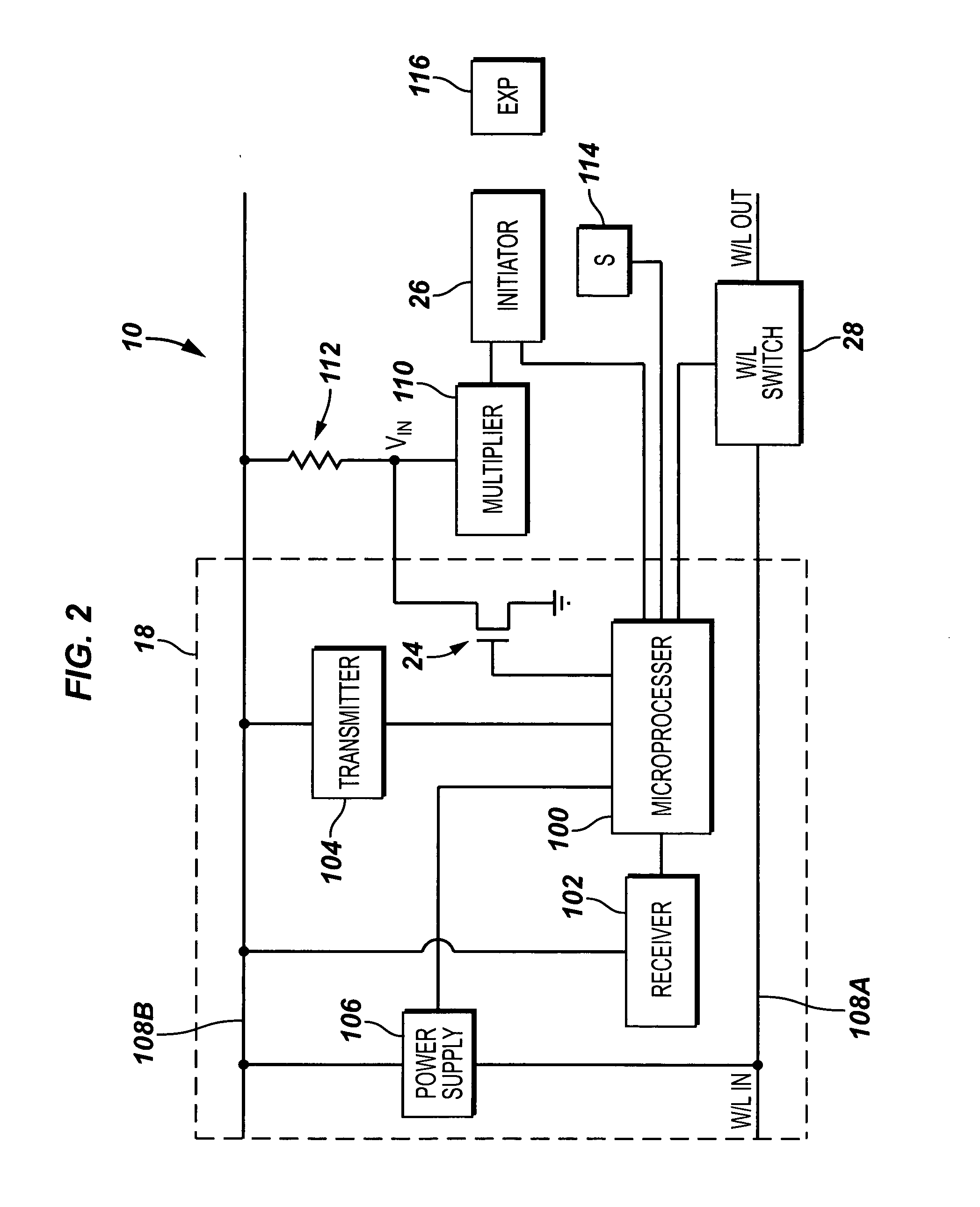
[0009] In general, methods and apparatus provide more secure communications with well tools. For example, a system includes a well tool for deployment in a well, a controller, and a link coupled between the controller and the well tool. The well tool includes plural control units, each of the plural control units having a microprocessor and an initiator coupled to the microprocessor. Each microprocessor is adapted to communicate bi-directionally with the controller. The controller is adapted to send a plurality of activation commands to respective microprocessors to activate the respective control units. Each activation command contains a unique identifier corresponding to a respective control unit.

Problems solved by technology

In some cases, activation of downhole tools creates safety concerns.
Another safety concern that exists at a well site is the use of wireless devices, especially radio frequency (RF), devices, which may inadvertently activate certain types of explosive devices.
As a result, wireless devices are usually not allowed at a well site, thereby limiting communications options that are available to well operators.
Yet another concern associated with using explosive devices at a well site is the presence of stray voltages that may inadvertently detonate explosive devices.
A further safety concern with explosive devices is that they may fall into the wrong hands.
Such explosive devices pose great danger to persons who do not know how to handle the explosive devices or who want to maliciously use the explosive devices to harm others.

Method used


Image

  • Secure activation of a downhole device
  • Secure activation of a downhole device
  • Secure activation of a downhole device

Examples


Embodiment Construction

[0015] In the following description, numerous details are set forth to provide an understanding of the present invention. However, it will be understood by those skilled in the art that the present invention may be practiced without these details and that numerous variations or modifications from the described embodiments may be possible.

[0016] As used here, the terms “up” and “down”; “upper” and “lower”; “upwardly” and downwardly”; “upstream” and “downstream”; “above” and “below”; and other like terms indicating relative positions above or below a given point or element are used in this description to more clearly describe some embodiments of the invention. However, when applied to equipment and methods for use in wells that are deviated or horizontal, such terms may refer to a left to right, right to left, or other relationship as appropriate.

[0017] Referring to FIG. 1, a system according to one embodiment includes a surface unit 16 that is coupled by cable 14 (e.g., a wireline)...


PUM


Abstract

A system includes a well tool for deployment in a well, a controller, and a link coupled between the controller and the well tool. The well tool comprises plural control units, each of the plural control units having a microprocessor and an initiator coupled to the microprocessor. Each microprocessor is adapted to communicate bi-directionally with the controller. The controller is adapted to send a plurality of activation commands to respective microprocessors to activate the respective control units. Each activation command containing a unique identifier corresponding to a respective control unit.

Description

CROSS-REFERENCE TO RELATED APPLICATIONS [0001] This is a continuation-in-part of U.S. Ser. No. 10 / 076,993, filed Feb. 15, 2002, which is a continuation-in-part of U.S. Ser. No. 09 / 997,021, filed Nov. 28, 2001, which is a continuation-in-part of U.S. Ser. No. 09 / 179,507, filed Oct. 27, 1998, now U.S. Pat. No. 6,283,227. [0002] This application also claims the benefit under 35 U.S.C. § 119(e) of U.S. Provisional Application Ser. No. 60 / 498,729, entitled, “Firing System for Downhole Devices,” filed Aug. 28, 2003. [0003] Each of the referenced applications is hereby incorporated by reference.TECHNICAL FIELD [0004] The invention relates generally to secure activation of well tools. BACKGROUND [0005] Many different types of operations can be performed in a wellbore. Examples of such operations include firing guns to create perforations, setting packers, opening and closing valves, collecting measurements made by sensors, and so forth. In a typical well operation, a tool is run into a well...

Claims


Application Information

Patent Timeline
Patent Type & Authority Applications(United States)
IPC IPC(8): E21B41/00E21B43/1185E21B43/119E21B47/12F42D1/05
CPCE21B41/00E21B41/0021E21B43/1185F42D1/05E21B43/119E21B47/12E21B43/11857
Inventor LERCHE, NOLAN C.BROOKS, JAMES E.WONG, CHOON FEI
Owner SCHLUMBERGER TECH CORP
Learn More