
Facet arthroplasty devices and methods

a facet arthroplasty and facial joint technology, applied in the field of facial joint surgery devices and methods, can solve the problems of slow fusion rate, arthrodesis poses problems of its own, poor treatment effect, etc., and achieve the effect of reducing or eliminating pain, and reducing or eliminating the incidence of spondylolisthesis

Inactive Publication Date: 2005-02-24
FACET SOLUTIONS
View PDF99 Cites 276 Cited by
  • Summary
  • Abstract
  • Description
  • Claims
  • Application Information

AI Technical Summary

Benefits of technology

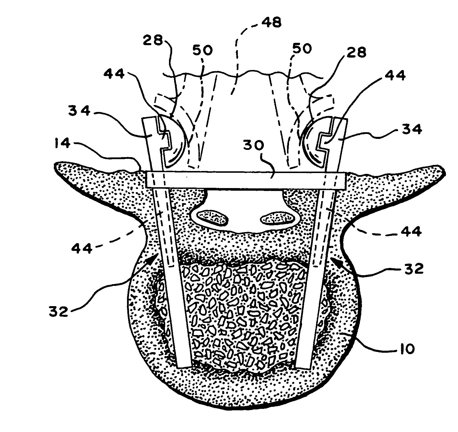
[0015] One aspect of the invention provides a facet joint prosthesis to replace, on a vertebral body, a caudal portion of a natural facet joint (e.g., a superior articular surface and supporting bone structure on the vertebral body). The caudal prosthesis comprises a component sized to be fixed to the vertebral body, e.g., on or near a pedicle. The caudal prosthesis includes an artificial facet joint structure adapted to replace a caudal portion of the natural facet joint after its removal from the vertebral body. The removal of a caudal portion of the natural facet joint and its total replacement by the artificial facet joint structure of the caudal prosthesis frees the orientation of the prosthesis from anatomic constraints imposed by a preexisting articular configuration of the caudal portion of the natural facet joint. Furthermore, the artificial facet joint structure of the caudal prosthesis can comprise an artificial articular configuration that is unlike the preexisting articular configuration, so that a desired articulation or bony anatomy can be restored to achieve a desired level of function.
[0017] Another aspect of the invention provides a facet joint prosthesis to replace, on a vertebral body, a cephalad portion of a natural facet joint (e.g., an inferior articular surface and supporting bone structure on the vertebral body). The cephalad prosthesis comprises a component sized to be fixed to the vertebral body, e.g., on or near a pedicle, or on or near a lamina, or on or near a spinous process, or combinations thereof. The cephalad prosthesis includes an artificial facet joint structure adapted to replace a cephalad portion of the natural facet joint after its removal from the vertebral body. As with the removal and total replacement of a caudal portion of the natural facet joint, the removal of a cephalad portion of the natural facet joint and its total replacement by the artificial facet joint structure of the cephalad prosthesis makes possible the orientation of the prosthesis free from anatomic constraints imposed by a preexisting articular configuration of the cephalad portion of the natural facet joint. Furthermore, like the caudal prosthesis, the artificial facet joint structure of the cephalad prosthesis can comprise an artificial articular configuration that is unlike the preexisting articular configuration of the natural facet surface (which is removed), so that a desired articulation or bony anatomy can be totally restored.
[0019] Another aspect of the invention provides a prosthesis assembly and related method for replacing a natural facet joint between adjoining first vertebral body and a second vertebral bodies. The assembly and method utilize a first component sized to be fixed to the first vertebral body, which is superior to the second vertebral body. The first component includes a first artificial facet joint structure adapted to replace a cephalad portion of the natural facet joint on the first vertebral body after removal of the cephalad portion of the natural facet joint from the first vertebral body. The assembly and method also comprise a second component sized to be fixed to the second vertebral body. The second component includes a second artificial facet joint structure adapted to replace the caudad portion of the natural facet joint of the second vertebral body after removal of the caudad portion of the natural facet joint from the second vertebral body. Together, the first and second artificial facet joint structures comprise an artificial facet joint. The removal of both cephalad and caudal portions of a natural facet joint and their total replacement by the artificial facet joint structures of the first and second components allows the artificial facet joint to be installed without anatomic constraints imposed by a preexisting articular configuration of the natural facet joint. The removal of the natural facet joints also removes bone spurs affecting the nerve roots adjacent the natural facet structures, alleviating or eliminating pain. Furthermore, the artificial facet joint structures of either the first or second components, or both, can create an artificial articular configuration for the artificial facet joint that is unlike the preexisting articular configuration of the removed natural facet joint, so that a desired articulation or bony anatomy can be completely restored. By restoring facet joint articulation to a desired level of function, the incidence of spondylolisthesis can be reduced or eliminated. Other features and advantages of the inventions are set forth in the following Description and Drawings, as well as in the appended claims.

Problems solved by technology

Furthermore, although patients with one or two levels of spinal stenosis tend to do reasonably well with just a one to two level wide decompressive laminectomy, patients whose spinal stenosis is associated with degenerative spondylolisthesis have not seen good results.
Although patients who undergo concomitant arthrodesis do demonstrate a significantly better outcome with less chance of further vertebral slippage after laminectomy, arthrodesis poses problems of its own.
Aside from the occurrence of further spondylolisthesis in some patients, additional effects include non-unions, slow rate of fusion even with autografts, and significant morbidity at the graft donor site.
Furthermore, even if the fusion is successful, joint motion is totally eliminated at the fusion site, creating additional stress on healthy segments of the spine which can lead to disc degeneration, herniation, instability spondylolysis, and facet joint arthritis in the healthy segments.
Although different designs achieve different levels of success with patients, disc replacement mainly helps patients with injured or diseased discs; disc replacement does not address spine pathologies such as spondylolisthesis and spinal stenosis caused by facet joint degeneration or disease.

Method used


Image

  • Facet arthroplasty devices and methods
  • Facet arthroplasty devices and methods
  • Facet arthroplasty devices and methods

Examples


Embodiment Construction

[0030] I. Anatomy of Lumbar Vertebrae

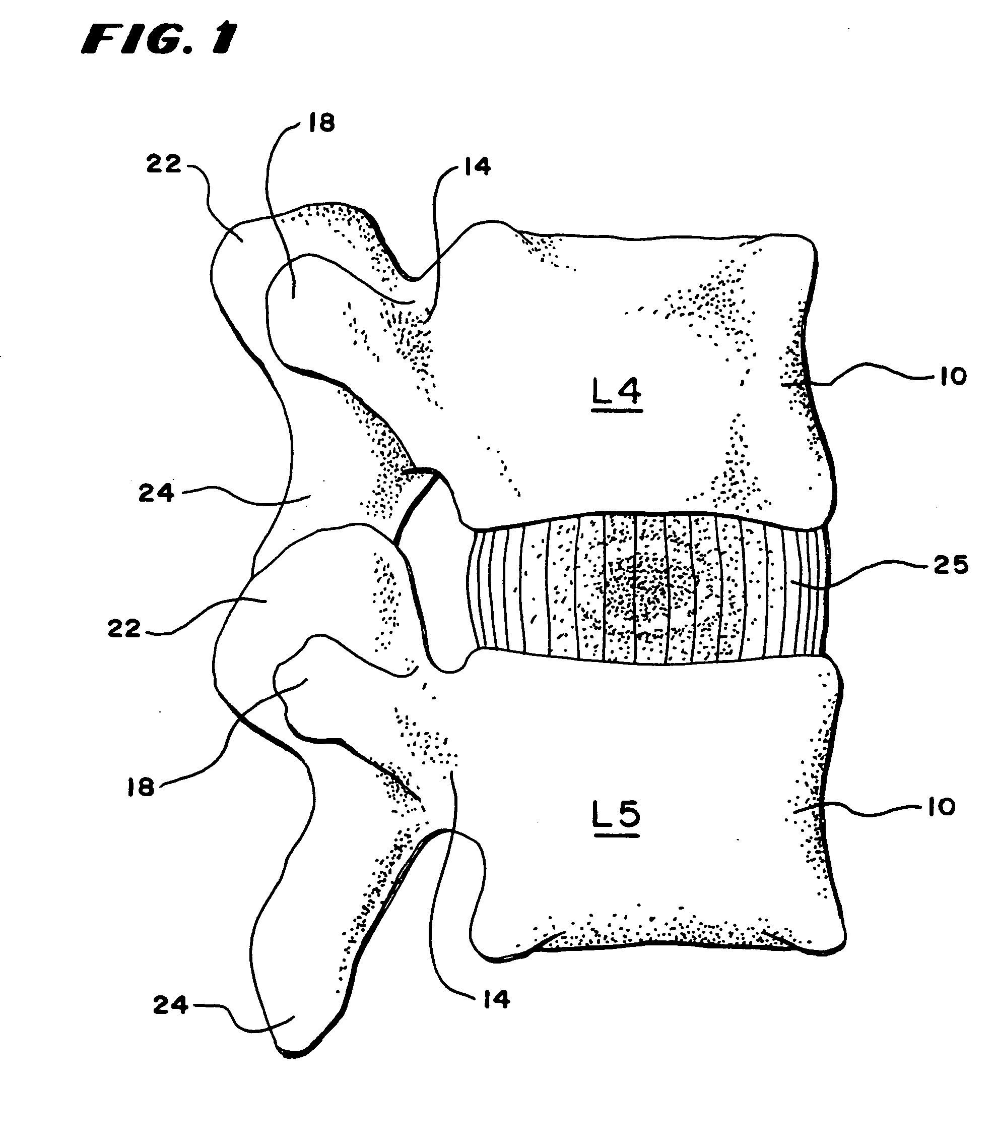
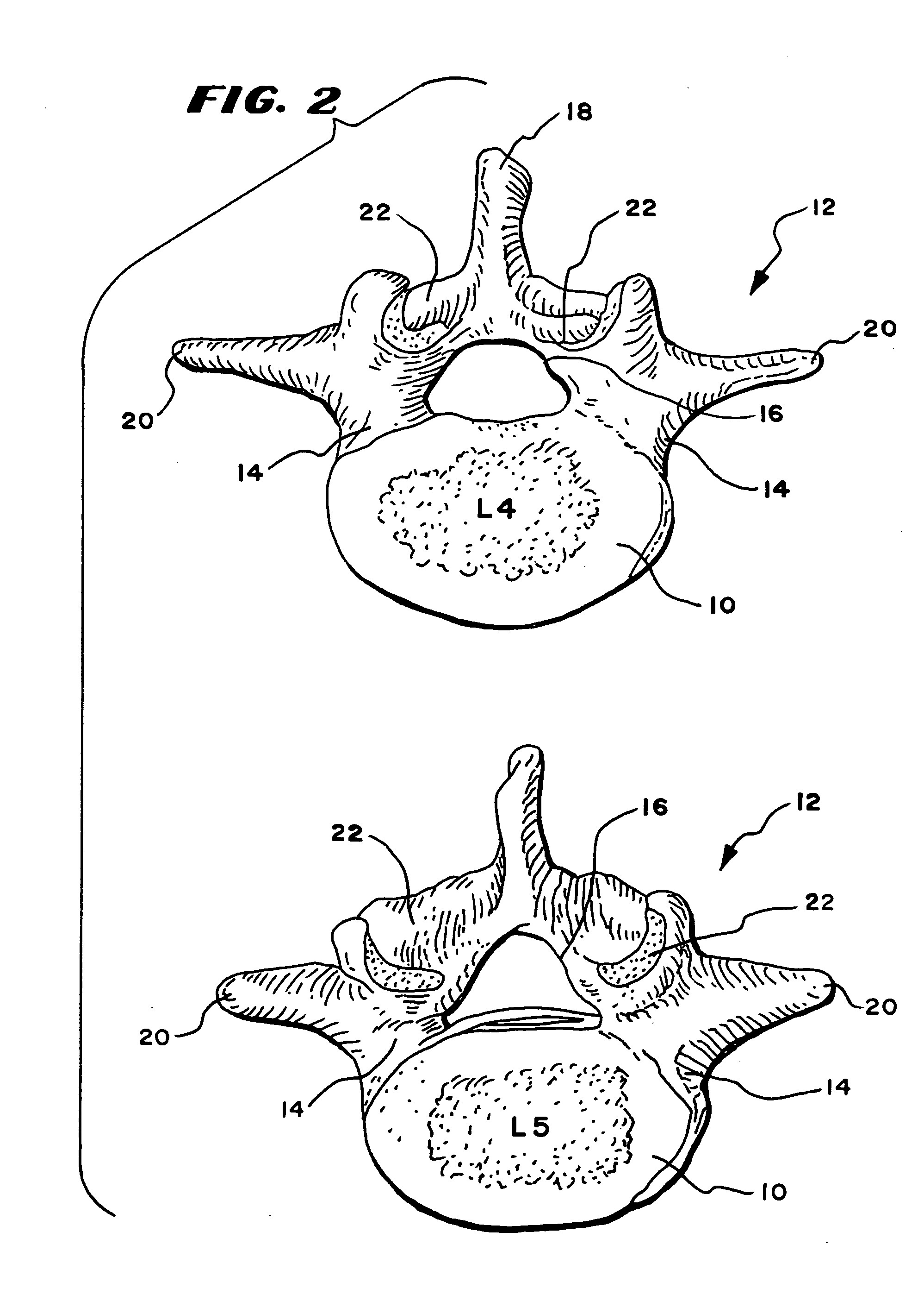
[0031]FIGS. 1 and 2 show the fourth and fifth lumbar vertebrae L4. and L5, respectively, in a lateral view (while in anatomic association) and in a superior view (separately). The lumbar vertebrae (of which there are a total of five) are in the lower back, also called the “small of the back.”

[0032] As is typical with vertebrae, the vertebrae L4 and L5 are separated by an intervertebral disk 25. The configuration of the vertebrae L4 and L5 differ somewhat, but each (like vertebrae in general) includes a vertebral body 10, which is the anterior, massive part of bone that gives strength to the vertebral column and supports body weight. The vertebral arch 12 is posterior to the vertebral body 10 and is formed by the right and left pedicles 14 and lamina 16. The pedicles 14 are short, stout processes that join the vertebral arch 12 to the vertebral body 10. The pedicles 14 project posteriorly to meet two broad flat plates of bone, called the lamina 1...


PUM

PropertyMeasurementUnit
stiffnessaaaaaaaaaa
lengthaaaaaaaaaa
strengthaaaaaaaaaa

Abstract

Surgically installed prostheses replace either the caudal portion of a natural facet joint, the cephalad portion of a natural facet joint, or both. The prostheses are readily attached to the pedicles of a vertebral body and support at least one element that defines an artificial facet joint structure. The caudal facet joint structure is sized and located to articulate with the cephalad facet joint structure. Together, the prostheses form a total facet replacement system. The system is suitable for use in virtually all levels of the spine.

Description

RELATED APPLICATIONS [0001] This application is a divisional of U.S. patent application Ser. No. 10 / 067,137, filed Feb. 4, 2002, which is a continuation-in-part of U.S. patent application Ser. No. 09 / 693,272, filed Oct. 20, 2000, entitled “Facet Arthroplasty Devices and Methods,” now U.S. Pat. No. 6,610,091, which claims the benefit of Provisional Patent Application Ser. No. 60 / 160,891, filed Oct. 22, 1999, and entitled “Facet Arthroplasty Devices and Methods,” all of which are incorporated herein by reference.FIELD OF THE INVENTION [0002] The present invention generally relates to devices and surgical methods for the treatment of various types of spinal pathologies. More specifically, the present invention is directed to several different types of facet joint replacement prostheses, surgical procedures for performing facet joint replacements, and surgical instruments which may be used to perform the surgical procedures. BACKGROUND OF THE INVENTION [0003] Back pain is a common human...

Claims


Application Information

Patent Timeline
Patent Type & Authority Applications(United States)
IPC IPC(8): A61B17/00A61B17/16A61B17/86A61F2/00A61F2/02A61F2/28A61F2/30A61F2/44A61F2/46
CPCA61B17/1671A61F2310/00976A61F2/28A61F2/4405A61F2002/30387A61F2002/30433A61F2002/305A61F2002/30537A61F2002/30604A61F2002/30777A61F2002/30874A61F2002/449A61F2002/4631A61F2220/0025A61F2220/0041A61F2250/0004A61F2310/00017A61F2310/00023A61F2310/00029A61F2310/00131A61F2310/00179A61F2310/00329A61F2310/00604A61F2310/00634A61F2310/0097A61B17/86A61F2002/30873A61F2002/30329
Inventor REILEY, MARK A.
Owner FACET SOLUTIONS
Learn More