
Robot with removable mounting elements

a technology of robots and mounting elements, which is applied in the field of hobby robots, can solve the problems of unproductive time in the build or modification process, inconvenient installation, and inability to maintain the robot, and achieve the effects of reducing the engineering quality and cosmetic appeal, quick and easy association with and secured, and easy mounting and removal

Inactive Publication Date: 2005-02-17
JAMES JEREMY
View PDF23 Cites 113 Cited by
  • Summary
  • Abstract
  • Description
  • Claims
  • Application Information

AI Technical Summary

Benefits of technology

"The invention is a hobby robot with a removable mounting system and an encasement shell. The support structure is modeled after industry standard personal computing cases, making it easy to add or modify hardware. The robot looks like a professionally engineered and aesthetically appealing platform, without the need for builders to improvise or seek outside assistance. The invention provides an affordable and accurate alternative to building a home-made robotic platform."

Problems solved by technology

Currently, manufactured robotic platforms are extremely crude, garage-built, proprietary units, as currently no build standards exist in the field of robotic platforms.
Although the fixed-shelf approach is appropriate for containing the hardware and related peripherals on the actual robot during actual use of the robot, the fixed-shelf approach is not conducive to continued upgrades or modifications that a builder may perform on the robot.
The removal of hardware only for the purposes of accessing other hardware adds unproductive time to the build or modification process.
This may result in added frustration on the part of the builder, as he or she may already be frustrated due to the fact that a certain intended aspect of building or modification is not proceeding or performing as intended.

Method used


Image

  • Robot with removable mounting elements
  • Robot with removable mounting elements
  • Robot with removable mounting elements

Examples


Embodiment Construction

[0018] For purposes of the description hereinafter, spatial or directional terms shall relate to the invention as it is oriented in the drawing figures. However, it is to be understood that the invention may assume various alternative variations, except where expressly specified to the contrary. It is also to be understood that the specific apparatus illustrated in the attached drawings, and described in the following specification, is simply an exemplary embodiment of the invention. Hence, specific dimensions and other physical characteristics related to the embodiments disclosed herein are not to be considered as limiting.

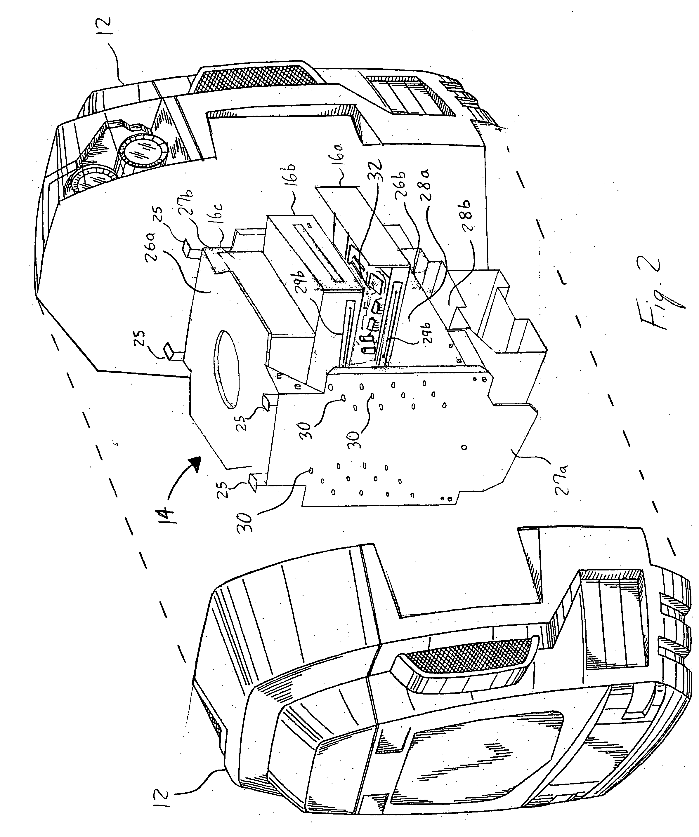
[0019]FIG. 1-3 depicts an exemplary embodiment of the present invention. Specifically, FIG. 1 depicts an exterior of a robot 10, such as a hobby robot, having an encasement shell 12. As shown in FIG. 2, the encasement shell 12 encloses a support structure 14, which in turn supports various mounting elements 16a-c. FIG. 3 depicts an exemplary embodiment of impart...


PUM


Abstract

A hobby robot having a support structure includes a cavity defined within the support structure, wherein the cavity includes means positioned within the cavity for removably coupling at least one mounting element to an interior portion of the cavity. The support structure also includes means for securing an encasement shell to the support structure. The mounting element may be a tray or hardware that performs a desired function in connection with the operation of the robot. The support structure is adapted to receive a self-contained power source and means for imparting motive force to the support structure.

Description

CROSS REFERENCE TO RELATED APPLICATIONS [0001] This application claims the benefit of U.S. Provisional Patent Application No. 60 / 494,533 filed Aug. 12, 2003, and entitled “Robotic Platform”, the contents of which are incorporated herein by reference.BACKGROUND OF THE INVENTION [0002] 1. Field of the Invention [0003] The present invention is directed to a hobby robot and, more specifically, to a support structure for use with the hobby robot. [0004] 2. Description of Related Art [0005] Building a robot from scratch is an excellent way to learn a lot about robotics, but is not the only way to get started. A robot kit that includes a pre-fabricated platform or support structure, motor, wheels, etc. can assist a builder through the initial learning curve and save a builder time, frustration and money, so that the builder can more quickly enter the programming or customizing aspects of robotics. [0006] Currently, manufactured robotic platforms are extremely crude, garage-built, proprieta...

Claims


Application Information

Patent Timeline
Patent Type & Authority Applications(United States)
IPC IPC(8): B25J5/00B25J9/00B25J19/00
CPCB25J5/007B25J19/0075B25J9/0009
Inventor BURICK, THOMAS J.
Owner JAMES JEREMY
Learn More