
Microfluidic rotary flow reactor matrix

a microfluidic rotary flow and reactor technology, applied in the direction of positive displacement liquid engines, instruments, laboratory glasswares, etc., can solve the problems of sample cross-contamination, limited sample species that have successfully been demonstrated so far, and scaled reagent consumption, so as to reduce labor, reduce pipetting steps, and save reagent consumption. the effect of scal

Inactive Publication Date: 2005-02-17
CALIFORNIA INST OF TECH
View PDF57 Cites 193 Cited by
  • Summary
  • Abstract
  • Description
  • Claims
  • Application Information

AI Technical Summary

Benefits of technology

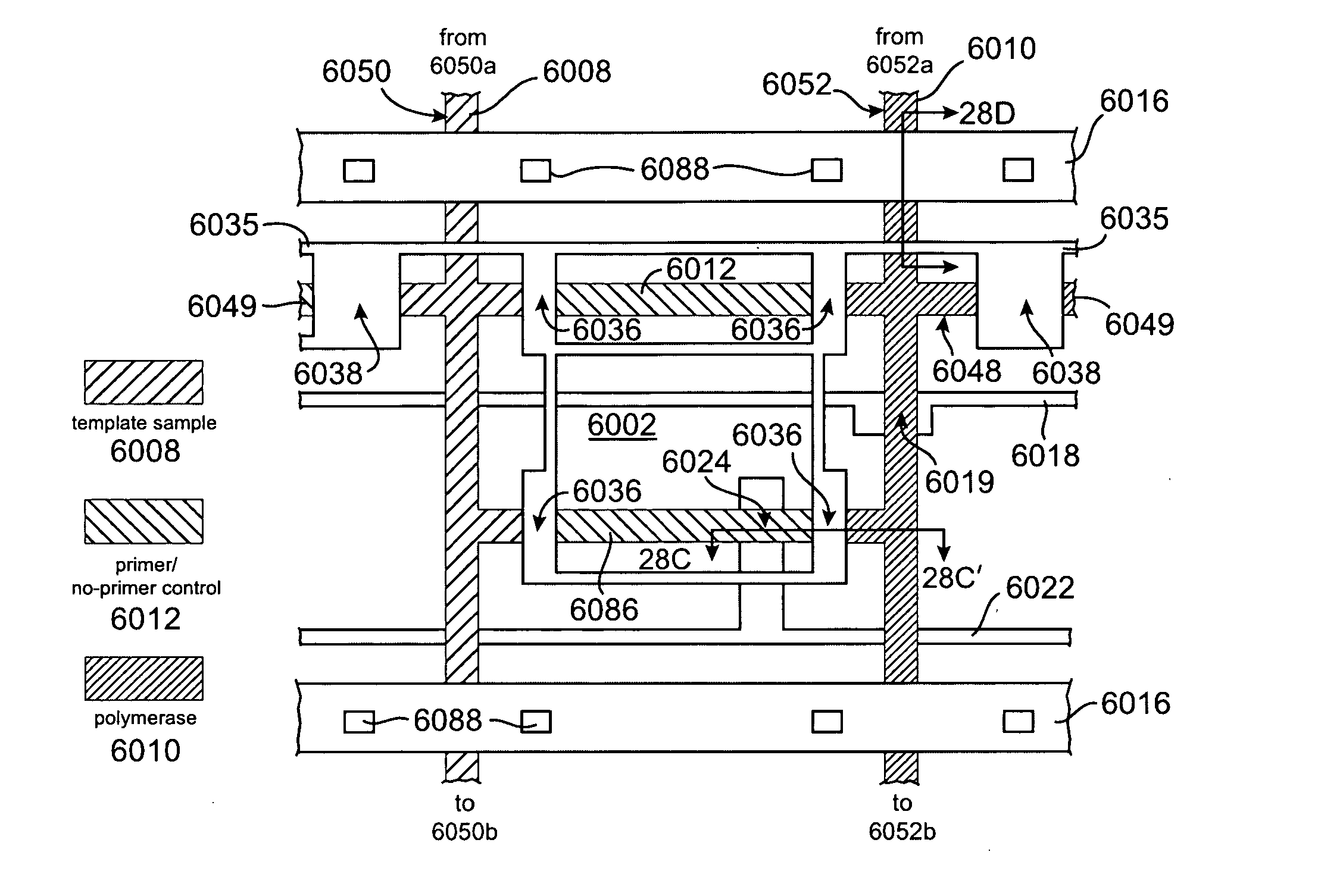
[0012] An embodiment of a microfluidic matrix device in accordance with the present invention offers an effective solution to the “world-to-chip” interface problem by accomplishing two important goals simultaneously: an economy of scale in reagent consumption is achieved, while simultaneously minimizing pipetting steps. N2 independent assays can be performed with only 2N+1 pipetting steps, using a single aliquot of the enzyme that can be amortized over all the reactors. Thus, the chip reduces labor relative to conventional fluid handling techniques by using an order of magnitude less pipetting steps and reduces cost by consuming two to three orders of magnitude less reagents per reaction. The demonstrated PCR format has immediate applications in medical diagnosis and gene testing. Beyond PCR, the microfluidic matrix chip provides a universal and flexible platform for biological and chemical assays that require parsimonious use of precious reagents and highly automated processing.

Problems solved by technology

Although integrated glass capillaries have been used to reduce sample consumption for simple titration between two reagents, these devices are fundamentally serial and have the possibility of sample cross-contamination during the loading process.
However, only a limited species of samples have successfully been demonstrated so far.
The challenge associated with realizing the desired economies of scale in microfluidic devices is to simultaneously reduce the number of pipetting steps needed to load the devices, while amortizing the sample volume from each pipetting step over a large number of independent assays.
However, in those devices the reagent consumption scaled only with N, which was so small that there were little practical savings.
Passive devices also have technical limitations in sample metering and device operation.
For example, precise pressure balancing was required during operation of the devices of Kikutani et al., and the kinetics of mixing were limited due to the static nature in the devices of Ismagilov et al.

Method used


Image

  • Microfluidic rotary flow reactor matrix
  • Microfluidic rotary flow reactor matrix
  • Microfluidic rotary flow reactor matrix

Examples


Embodiment Construction

[0070] Unless defined otherwise, all technical and scientific terms used herein have the meaning commonly understood by a person skilled in the art to which this invention belongs. The following references provide one of skill with a general definition of many of the terms used in this invention: Singleton et al., DICTIONARY OF MICROBIOLOGY AND MOLECULAR BIOLOGY (2d ed. 1994); THE CAMBRIDGE DICTIONARY OF SCIENCE AND TECHNOLOGY (Walker ed., 1988); THE GLOSSARY OF GENETICS, 5TH ED., R. Rieger et al. (eds.), Springer Verlag (1991); and Hale & Marham, THE HARPER COLLINS DICTIONARY OF BIOLOGY (1991). As used herein, the following terms have the meanings ascribed to them unless specified otherwise.

[0071] A “flow channel” refers generally to a flow path through which a solution can flow.

[0072] The term “valve” unless otherwise indicted refers to a configuration in which a flow channel and a control channel intersect and are separated by an elastomeric membrane that can be deflected into ...


PUM

PropertyMeasurementUnit
Pressureaaaaaaaaaa
Flow rateaaaaaaaaaa
Widthaaaaaaaaaa

Abstract

A microfluidic device comprises a matrix of rotary flow reactors. The microfluidic matrix device offers a solution to the “world-to-chip” interface problem by accomplishing two important goals simultaneously: an economy of scale in reagent consumption is achieved, while simultaneously minimizing pipetting steps. N2 independent assays can be performed with only 2N+1 pipetting steps, using a single aliquot of enzyme amortized over all reactors. The chip reduces labor relative to conventional fluid handling techniques by using an order of magnitude less pipetting steps, and reduces cost by consuming two to three orders of magnitude less reagents per reaction. A PCR format has immediate applications in medical diagnosis and gene testing. Beyond PCR, the microfluidic matrix chip provides a universal and flexible platform for biological and chemical assays requiring parsimonious use of precious reagents and highly automated processing.

Description

CROSS-REFERENCE TO RELATED APPLICATIONS [0001] The instant nonprovisional patent application claims priority from U.S. provisional patent application No. 60 / 494,432, filed Aug. 11, 2003. This previously filed provisional patent application is hereby incorporated by reference for all purposes.STATEMENT AS TO RIGHTS TO INVENTIONS MADE UNDER FEDERALLY SPONSORED RESEARCH AND DEVELOPMENT [0002] Work described herein has been supported, in part, by the NSF XYZ on a chip program and by the DARPA Bioflips program. The United States Government may therefore have certain rights in the invention. BACKGROUND OF THE INVENTION [0003] As described by at least Mitchell in Nat. Biotechnol. 19, 717-721 (2001), incorporated by reference herein for all purposes, microfluidic technology offers many possible benefits in chemistry, biology and medicine. One important possible benefit is to automate rote work while reducing the consumption of expensive reagents to the nanoliter or sub-nanoliter scale. [000...

Claims


Application Information

Patent Timeline
IPC IPC(8): B01J19/00B01L3/00B01L7/00C12M1/36C12NC12P19/34F04B43/04
CPCB01J19/0093F04B43/043B01J2219/00828B01J2219/00833B01J2219/00891B01J2219/0095B01L3/5025B01L3/502707B01L3/502715B01L3/50273B01L3/502738B01L7/52B01L2200/10B01L2300/0816B01L2300/0819B01L2300/0861B01L2300/088B01L2300/123B01L2300/1827B01L2400/0481B01L2400/0655B01J2219/00783G01N2035/00158F04B43/14C12Q1/68B81B3/00
Inventor LIU, JIANHANSEN, CARL L.QUAKE, STEPHEN R.
Owner CALIFORNIA INST OF TECH
Learn More