
Image-forming machine

Active Publication Date: 2005-02-17
KYOCERA DOCUMENT SOLUTIONS INC
View PDF3 Cites 10 Cited by
  • Summary
  • Abstract
  • Description
  • Claims
  • Application Information

AI Technical Summary

Benefits of technology

[0005] It is an object of the present invention to provide a novel image-forming machine which is capable of copying or printing images onto papers of various sizes, evenly utilizes nearly the whole transfer region of the photosensitive material drum in the direction of width to maintain stability in the image-forming characteristics and to lengthen the life of the photosensitive material drum.
[0006] Another object of the present invention is to provide a novel image-forming machine which is capable of copying or printing images onto papers of various sizes, improving productivity and efficiency.
[0007] A further object of the present invention is to provide a novel image-forming machine which is capable of copying or printing images onto papers of various sizes, and makes it possible to sort the discharged papers depending upon the sizes.
[0008] A still further object of the present invention is to provide a novel image-forming machine which is capable of copying or printing images onto papers of various sizes, decreases the frequency for exchanging the rolled papers, facilitates the exchanging operation and reduces the burden of work.
[0014] It is desired that the two rolled papers having smaller widths can be fed independently from each other.
[0018] It is desired that the two rolled papers having smaller widths can be fed independently from each other.

Problems solved by technology

When the images are copied or printed onto small-size papers having widths smaller than the papers having a maximum width by using the above-mentioned conventional image-forming machine, however, the central portion of the transfer region of the photosensitive drum in the direction of width is excessively utilized, causing the image-forming characteristics to lose stability, shortening the life of the photosensitive material drum due to excess of fatigue in the central portion and, further, arousing such problems as low productivity and efficiency, without being capable of sorting the discharged papers depending upon the sizes.
In order for the images to be copied or printed onto the papers of various sizes, further, it becomes necessary to frequently exchange the rolled papers requiring cumbersome exchanging operation and increased burden of work.

Method used


Image

  • Image-forming machine
  • Image-forming machine
  • Image-forming machine

Examples


Embodiment Construction

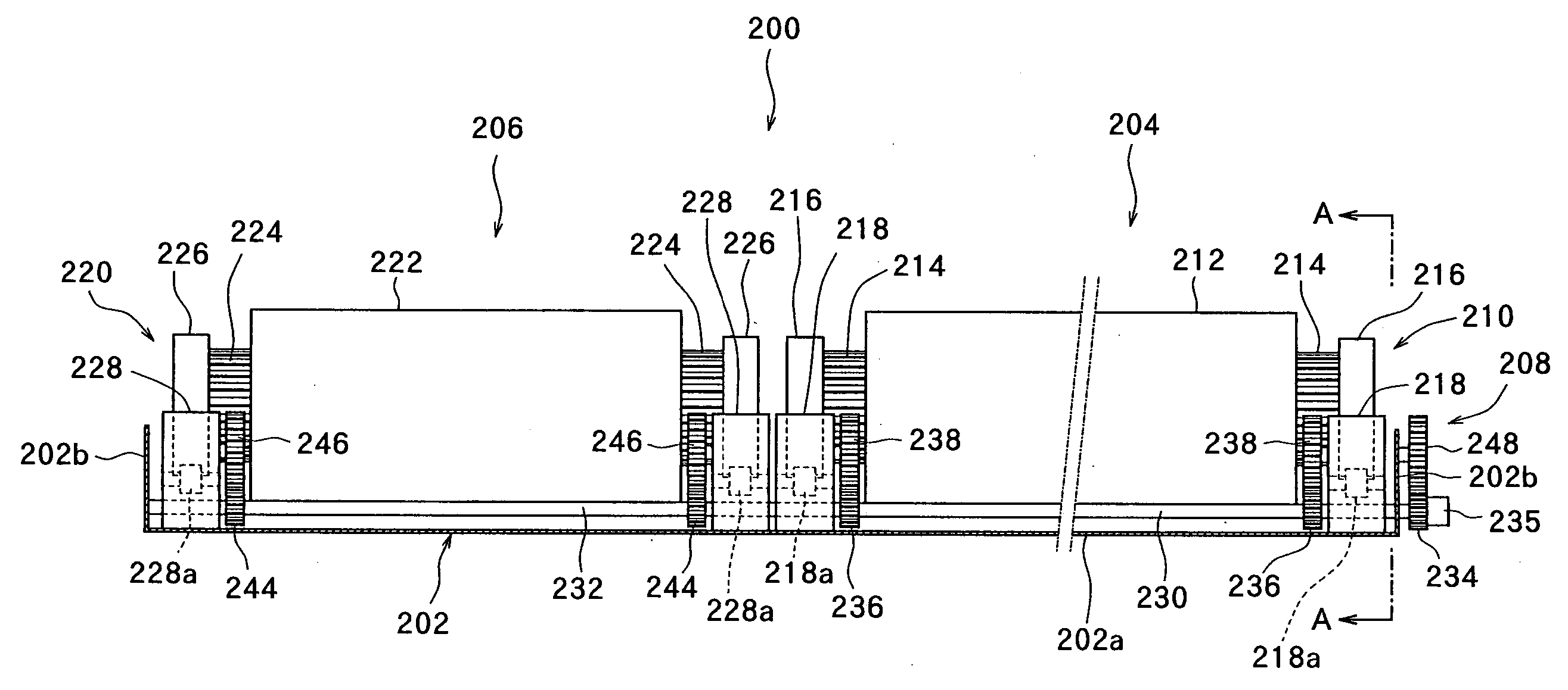
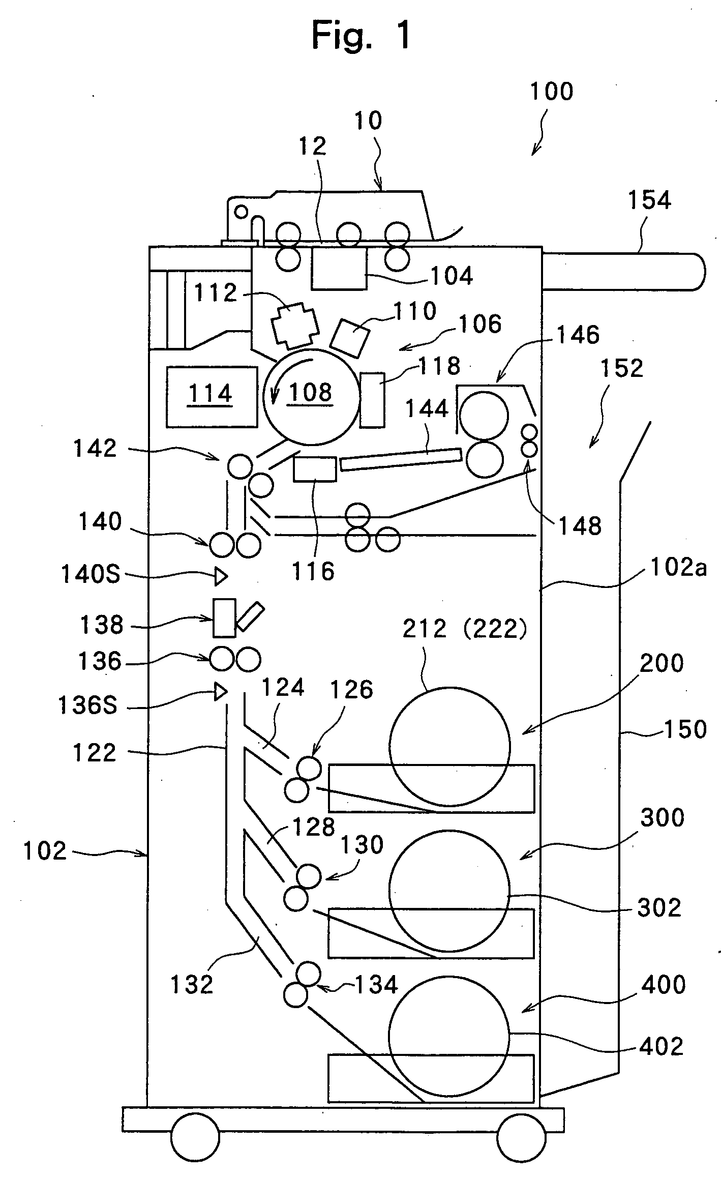
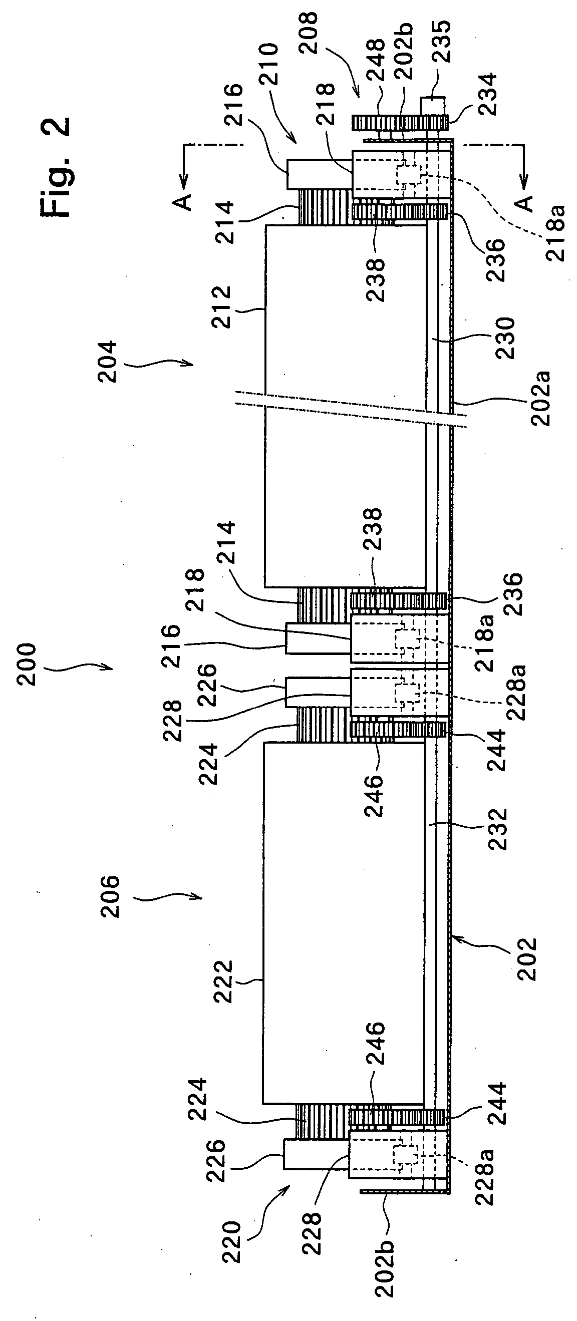
[0035] Preferred embodiments of an image-forming machine constituted according to the present invention will now be described in further detail with reference to the accompanying drawings.

[0036] Referring to FIG. 1, an electrostatic copier generally designated at 100 has a copier body 102 of nearly a rectangular parallelepiped shape. A document conveying device 10 is provided at an upper end of the copier body 102. A closely contacted-type image sensor 104 is arranged at an upper end in the copier body 102 but right under the document conveying device 10. An image-forming means 106 is arranged under the closely contacted-type image sensor 104. The image-forming means 106 has a photosensitive material drum 108 which is rotated in the counterclockwise direction in FIG. 1 by a drive means that is not shown.

[0037] The photosensitive material drum 108 is surrounded by a main charger 110 which homogeneously charges the surface of the photosensitive material drum 108, an LED print head 1...


PUM

PropertyMeasurementUnit
Sizeaaaaaaaaaa
Widthaaaaaaaaaa

Abstract

A copier comprising rolled paper accommodation units in which the rolled papers are installed, paper feed rollers and paper conveying rollers for conveying the papers delivered from the rolled papers along a paper conveying passage, a cutter and an image-forming means. A plurality of conveyance reference positions are set in the transfer region in a direction of conveying width so as to be corresponded to the sizes in the direction of conveying width of the papers passing through the transfer region of the image-forming means. The rolled papers are installed in the rolled paper accommodation units correspondingly to the conveyance reference positions.

Description

FIELD OF THE INVENTION [0001] The present invention relates to an image-forming machine such as an electrostatic copying machine, a printer or a facsimile capable of forming images on papers of large sizes, such as papers of JIS A0-size and A1-size. DESCRIPTION OF THE RELATED ART [0002] It has been desired that the image-forming machines capable of forming images on papers of large sizes are so constituted as to also form images, i.e., to copy or print images even on papers of A2- to A4-sizes in addition to papers of large sizes such as JIS A0- and A1-sizes. In order to satisfy the requirement of copying or printing images onto the papers of such multiplicity of sizes, it is a generally accepted practice to provide a plurality of rolled paper units comprising roll bodies and rolled papers wound on the roll bodies depending upon the widths of the papers and install them in the body of an image-forming machine in the up-and-down direction in a manner to be freely removed (e.g., see Ja...

Claims


Application Information

Patent Timeline
IPC IPC(8): B41J15/18G06F13/00B65H16/02B65H20/02B65H35/04G03G15/00G06F15/00
CPCB65H16/021G03G15/6558B65H20/02B65H35/04B65H2301/121B65H2301/413683B65H2301/41374B65H2403/942B65H2404/147B65H2511/12B65H2801/09B65H2801/12B65H2801/39G03G15/6517G03G15/652G03G15/6523G03G2215/00367G03G2215/00455B65H16/08B65H2220/09B65H2220/01B65H2220/04
Inventor MATSUOKA, KEIJI
Owner KYOCERA DOCUMENT SOLUTIONS INC
Learn More