Operating device for manual actuation of hoisting equipment

a technology of hoisting equipment and operating device, which is applied in the direction of operation facilitation, electrical apparatus, switch side location, etc., can solve the problems of high cost, high manufacturing and assembly costs, and inability to use the familiar and cheap standard pushbuttons. , to achieve the effect of simple and economical layout and large switch for

Active Publication Date: 2005-02-17
KONECRANES GLOBAL
View PDF3 Cites 19 Cited by
  • Summary
  • Abstract
  • Description
  • Claims
  • Application Information

AI Technical Summary

Benefits of technology

The invention is an operating device for manual actuation of hoisting equipment that ensures safety-relevant requirements for a distinct switching distance and sufficient switch forces in a simple and economical layout. The device uses a pressure activation mechanism consisting of an outer plunger and an inner plunger, with the first micro-key button activating the inner plunger and the additional control or switch element activating the outer plunger. The separation between electrical switching and mechanical activation allows for the use of standard commercial electrical switches for the actual electrical switching. The invention also proposes a design with at least one additional control or switch element that can switch between slow and fast speed, and a design with a bearing surface to activate the first micro-key button and a spring element to adjust the contact travel and switching force. The invention also proposes a flexible protective cap to seal off the pressure activation mechanisms from dirt and moisture, and a sample embodiment of the operating device with at least two spring-loaded locking lugs and locking grooves in the individual switch positions of the operating device.

Problems solved by technology

Control signals for hoisting equipment are often generated in practice with specially developed pushbuttons, whose manufacture involves high expense on parts, material, and assembly.
Although these familiar switches have worked very well in practice, their manufacture and assembly involve high cost.
Based on the mentioned need for distinct and long switching distances, it has not been possible thus far to use the familiar and cheap standard pushbuttons, since these have only very short switching distances and low switch forces.

Method used


Image

  • Operating device for manual actuation of hoisting equipment
  • Operating device for manual actuation of hoisting equipment
  • Operating device for manual actuation of hoisting equipment

Examples


Embodiment Construction

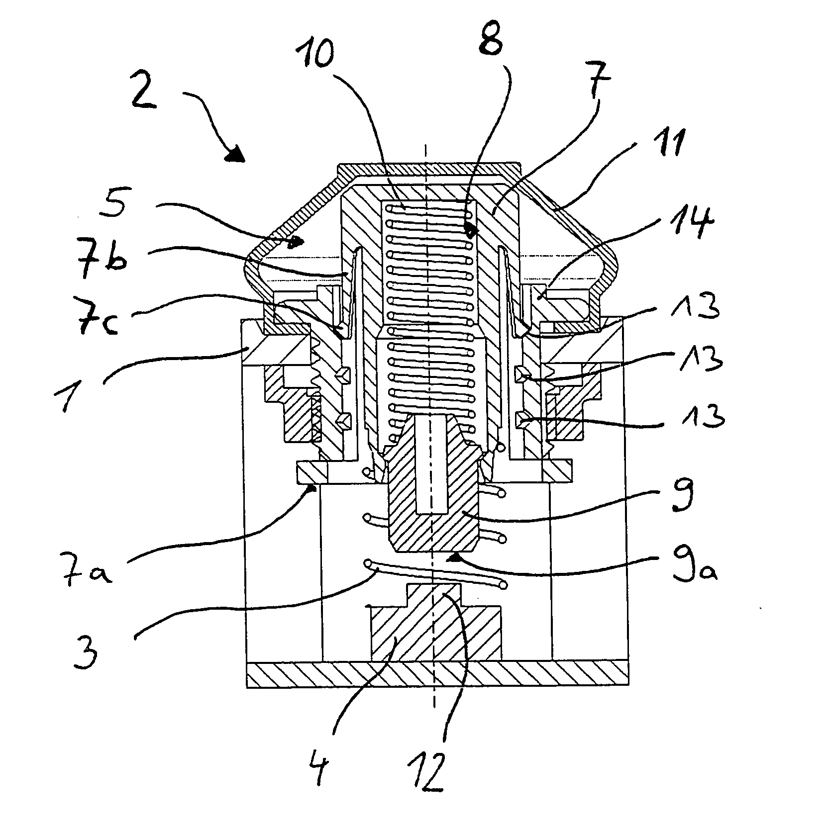
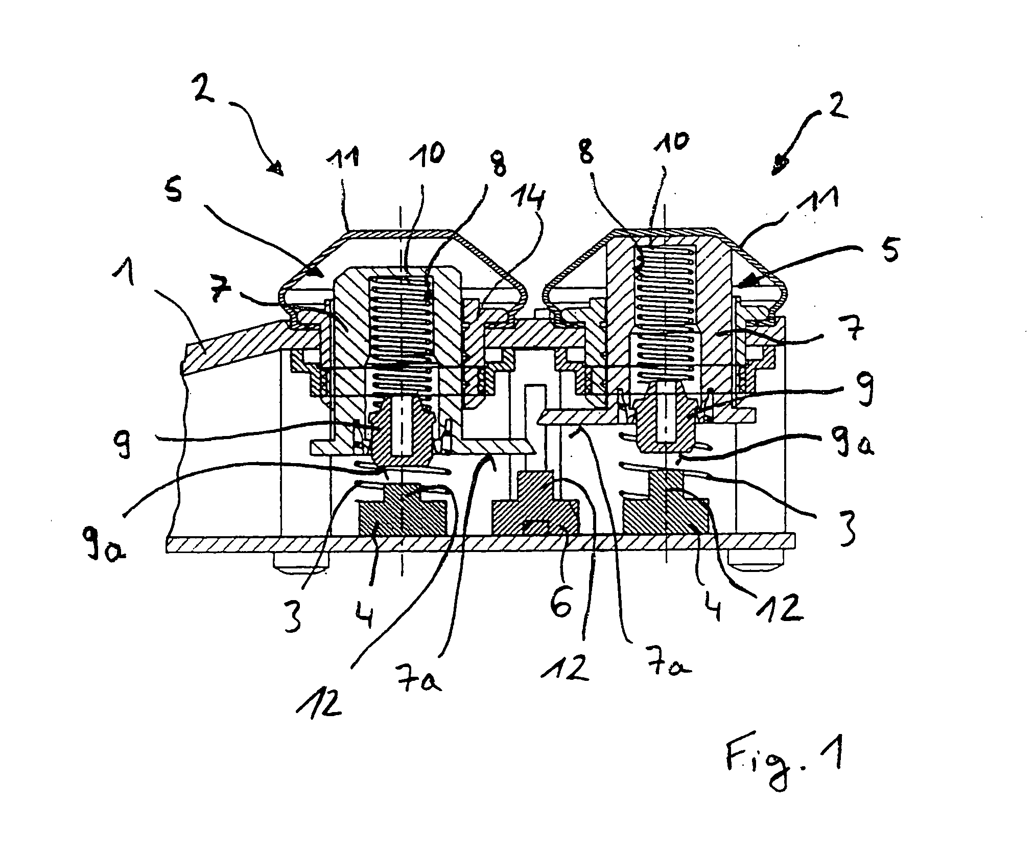
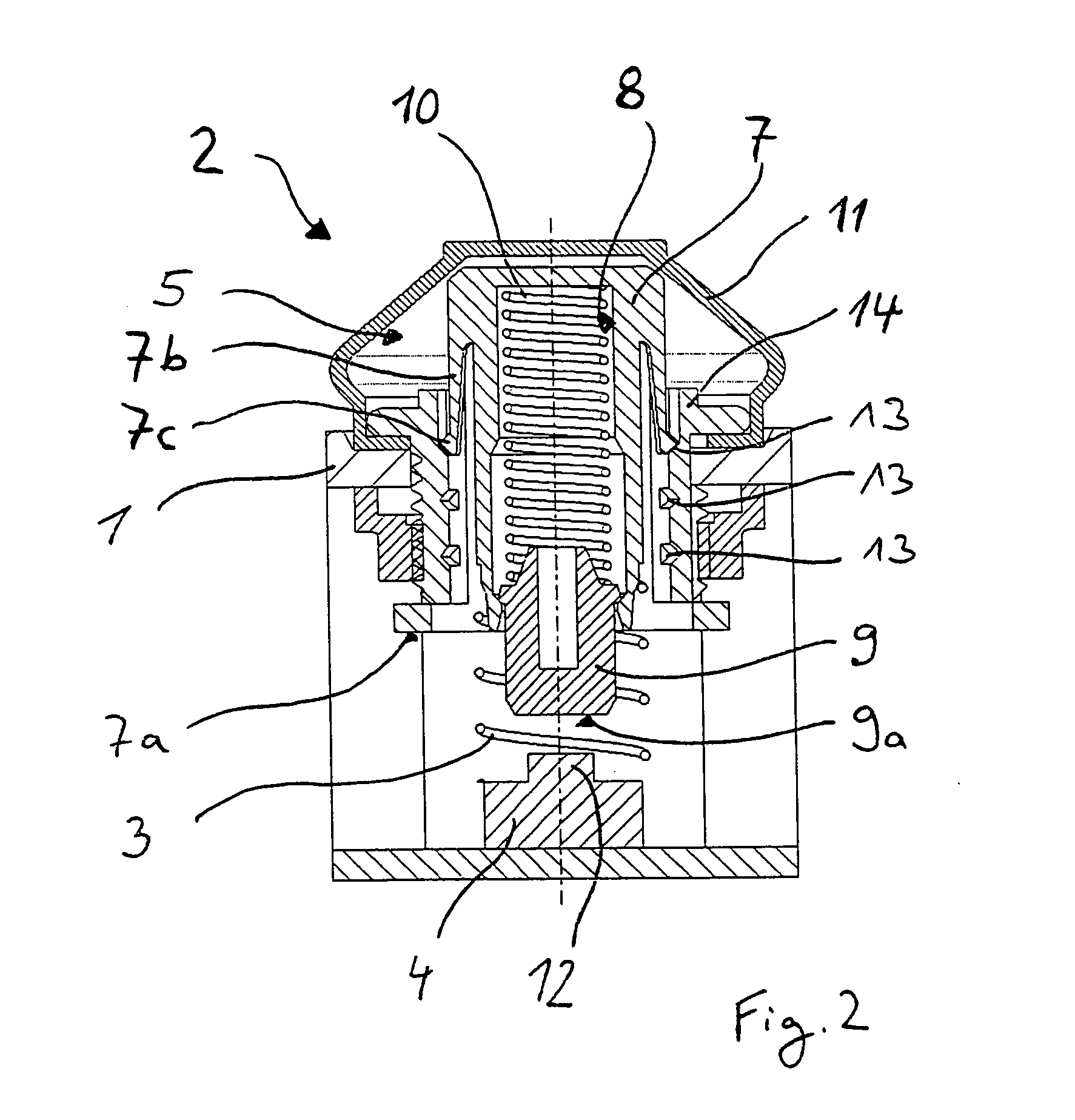
[0021] The sample embodiment shown partially in FIG. 1 for an operating device for the manual actuation of hoisting equipment essentially consists of switch housing 1 and two switch elements 2 arranged in the switch housing 1. These two switch elements 2 serve to activate the two possible different directions of movement of the hoisting device, namely lifting and lowering.

[0022] For safety reasons, the switch elements 2 of an operating device for the manual actuation of hoisting equipment must be designed so that a switch element 2 that is activated is returned at once to the basic off position as soon as no further pressure is exerted on the switch element 2. For this purpose, each switch element 2 is preloaded by a spring element 3 in the direction of the basic off position.

[0023] As is further evident from the diagram, each of the two switch elements 2 consists of an electrical first micro-key button 4 and a preceding pressure activation mechanism 5, by which the first micro-ke...


PUM


Abstract

An operating device for the manual actuation of hoisting equipment, with at least one spring-loaded switch element (2) for each direction of movement of the lifting device arranged in a switch housing (1), wherein each switch element (2) includes a pressure activation mechanism (5), a first electrical micro-key button (4), and at least one additional control or switch element, especially another electrical micro-key button (6), and the pressure activation mechanism (5) is arranged in front of the micro-key button (4) and the additional control or switch element and these can be activated in succession by means of such structure.

Description

BACKGROUND OF THE INVENTION [0001] The invention is directed to an operating device for the manual actuation of hoisting equipment and, in particular, to such an operating device with at least one spring-loaded switch element arranged in a switch housing for each direction of movement of the hoisting device. [0002] Control signals for hoisting equipment are often generated in practice with specially developed pushbuttons, whose manufacture involves high expense on parts, material, and assembly. Because the force / travel relationship of the pushbutton must be of such kind that the operating personnel can easily find and effortlessly maintain the intended position of the thumb for activation of the pushbutton, even when wearing work gloves, one requires switching distances of at least 5 mm, on the one hand, and clearly distinguishable locking positions for fast and slow operation, on the other. [0003] From DE 44 12 557 C2, one such special component is known for converting an actuation...

Claims


Application Information

Patent Timeline
Patent Type & Authority Applications(United States)
IPC IPC(8): H01H13/64
CPCH01H13/64H01H2235/03H01H2225/018H01H2217/02
Inventor KREBS, WOLFGANGFREITAG, HOLGERMUNZEBROCK, ANTONHASENACK, BURKHARDPERSICO, GIULIANOAPPEL, ERIKELSPASS, STEFAN
Owner KONECRANES GLOBAL
Why Eureka
Try Eureka