
Strap of a zipper

a zipper and strap technology, applied in the field of straps, can solve the problems of reducing the vision effect of the pattern or image, the pattern or the image printed on the cloth by screen printing cannot show a three-dimensional effect, and the problem of the pattern and image printed by screen printing remains. to achieve the effect of improving the strap of the zipper

Inactive Publication Date: 2005-02-17
YU CHIH HSIUNG
View PDF8 Cites 7 Cited by
  • Summary
  • Abstract
  • Description
  • Claims
  • Application Information

AI Technical Summary

Benefits of technology

[0009] The main objective of the present invention is to provide an improved strap of a zipper. The strap can show a special pattern and image on the strap.

Problems solved by technology

Consequently, the pattern or image may be detached from the cloth due to washing or friction and the weave grain of the cloth may reduce the vision effect of the pattern or the image.
Furthermore, the pattern or the image printed on the cloth by screen printing cannot show a three-dimension effect.
However, the problems of the pattern and image printed by screen printing is still remained in the printing method.
However, the weave grain still reduces the vision effect of the pattern or the image on the conventional strap of the zipper.

Method used


Image

  • Strap of a zipper
  • Strap of a zipper
  • Strap of a zipper

Examples


Embodiment Construction

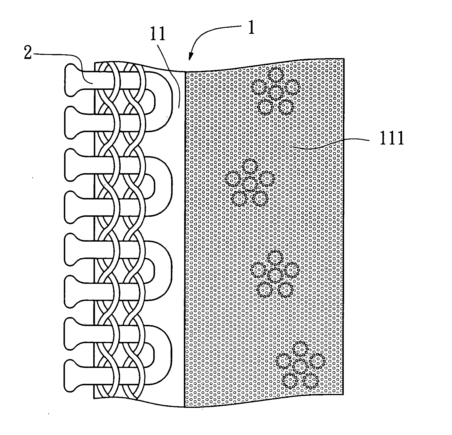
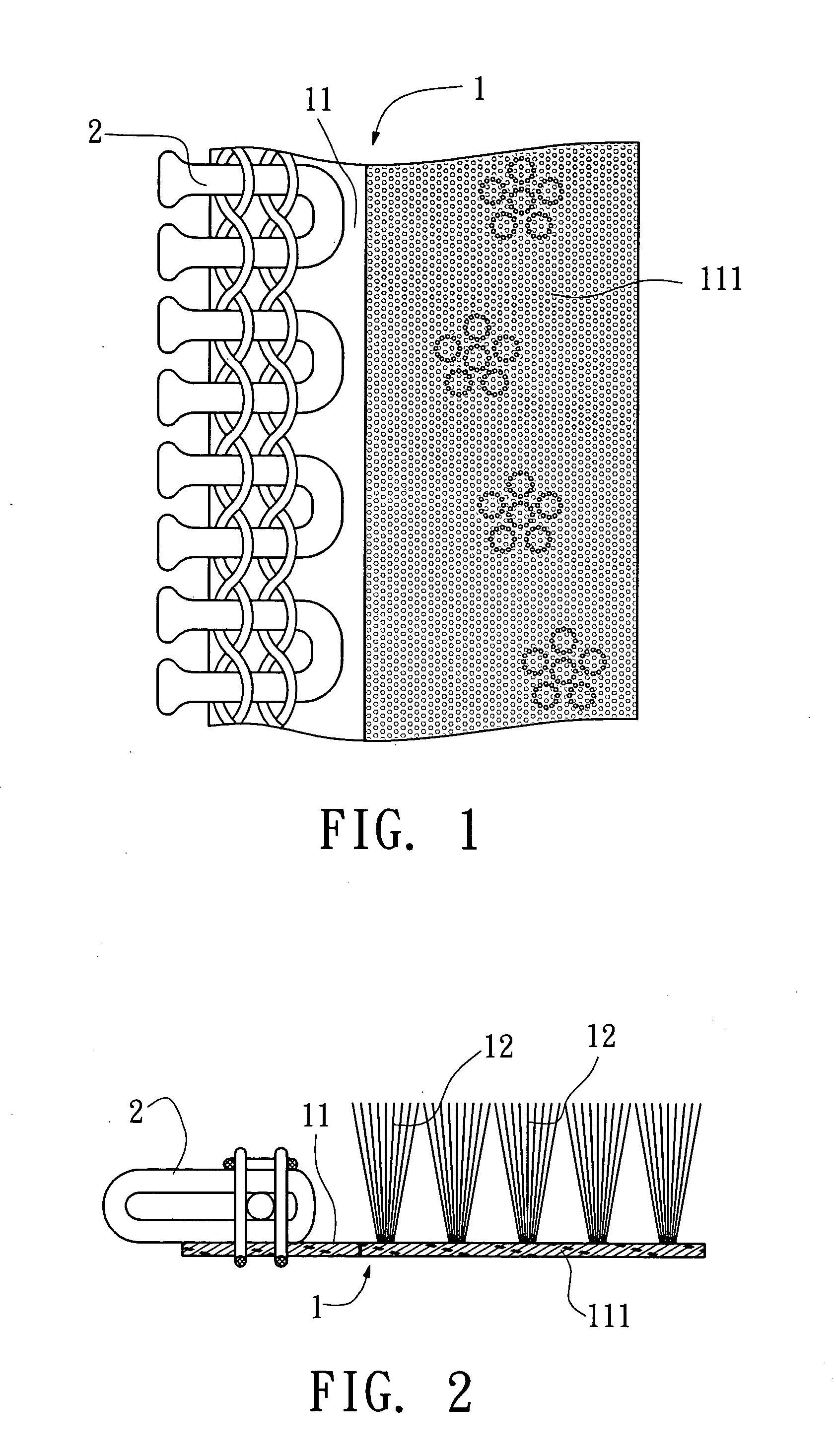
[0015] Referring to the drawings and initially to FIGS. 1 and 2, a strap (1) of a zipper in accordance with the present invention comprises a stitch portion (11) longitudinally formed on a first side of the strap (1) and a dress portion (111) longitudinally formed on a second side of the strap (1) adjacent to the stitch portion (11). A series of teeth (12) is longitudinally secured on the stitch portion (11) for engaging to a series of teeth of an adjacent strap (1). Multiple naps (12) upwardly extend from the dress portion (111) of the strap (1). The multiple naps (12) have a variety of colors to show a special pattern or image on the strap (1) in accordance with the present invention.

[0016] The stitch portion (11) of the strap (1) has no nap such that a block due to the naps (12) is never occurred when operating the zipper including the straps (1) of the present invention. The naps (12) each has a certain length such that the naps (12) of the present invention can cover the weave...


PUM


Abstract

A strap of a zipper includes a stitch portion longitudinally formed on a first side of the strap and a dress portion longitudinally formed on a second side of the strap adjacent to the stitch portion. A series of teeth is longitudinally secured on the stitch portion for engaging to a series of teeth of an adjacent strap. Multiple naps upwardly extend from the dress portion of the strap to show a special pattern and image on the strap.

Description

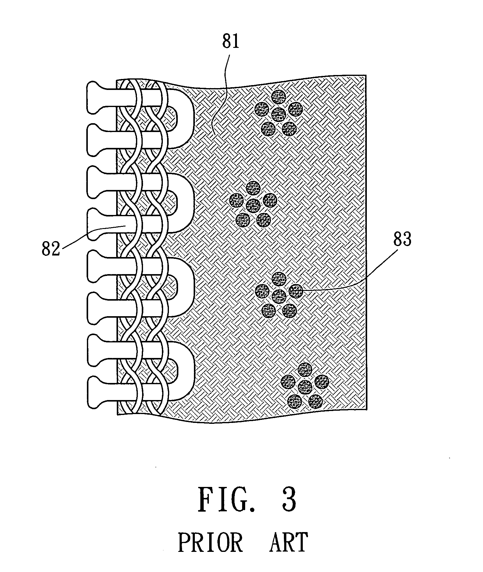
BACKGROUND OF THE INVENTION [0001] 1. Field of the Invention [0002] The present invention relates to a strap, and more particularly to a strap of a zipper. [0003] 2. Description of Related Art [0004] A conventional strap (81) of a zipper in accordance with the prior art shown in FIG. 3 has one side opposite to a series of the teeth (82) showing a pattern (83) for promoting vision effect. The pattern (83) is shown on the strap (81) by the following method. [0005] 1. Screen Printing: The pattern of image has a weak adhesion when being printed by screen printing. Consequently, the pattern or image may be detached from the cloth due to washing or friction and the weave grain of the cloth may reduce the vision effect of the pattern or the image. Furthermore, the pattern or the image printed on the cloth by screen printing cannot show a three-dimension effect. [0006] 2. Thermal Transfer Printing: The pattern or image printed on the cloth by thermal transfer printing has an adhesion slight...

Claims


Application Information

Patent Timeline
Patent Type & Authority Applications(United States)
IPC IPC(8): A44B19/34
CPCY10T24/2529A44B19/34
Inventor YU, CHIH HSIUNG
Owner YU CHIH HSIUNG
Learn More