Voltage collapse diagnostic and ATC system
a voltage collapse and diagnostic technology, applied in the direction of electric variable regulation, process and machine control, instruments, etc., can solve the problems of voltage collapse, subsystem stability loss, overload of additional power system components, etc., to improve or reduce reliability
- Summary
- Abstract
- Description
- Claims
- Application Information
AI Technical Summary
Benefits of technology
Problems solved by technology
Method used
Image
Examples
example 1
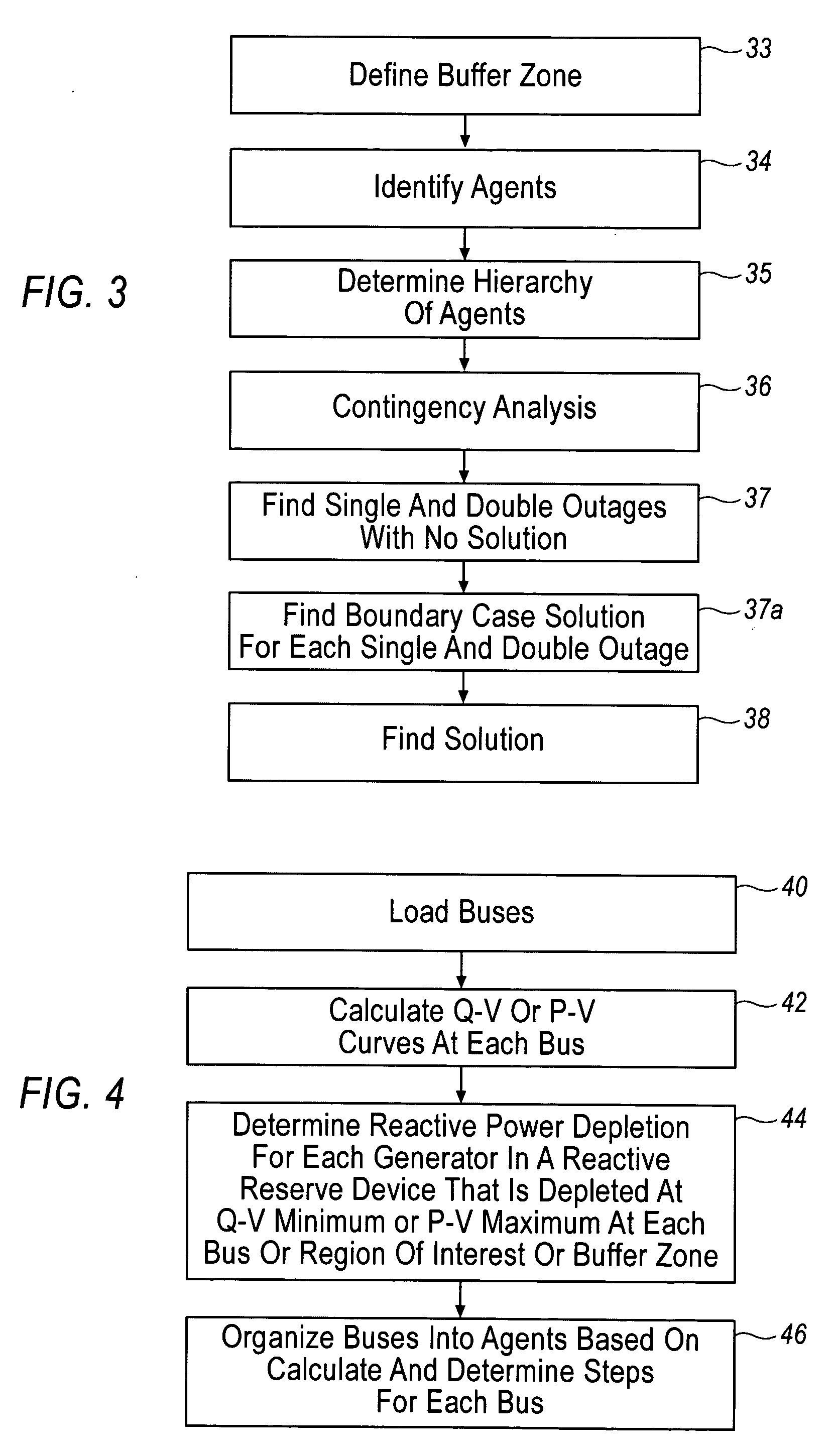
By way of a non-limiting hypothetical example, the above-described process is explained in conjunction with an example based on the Tables set forth below. In Table 1, the leftmost column identifies each specific bus of an area in the determined buffer zone in the electrical power system that is under study. The middle column in Table 1 defines the actual loads on the respective buses listed in the Table. The rightmost column defines the reactive reserves or generators that are depleted at the point of maximum load for the specific bus using a stress test such as a VQ curve. For the purpose of this example, reactive reserves are listed only as generators. The generators referenced in the Table correspond to the generators listed in FIG. 5.
TABLE 1Reactive Reserves of busesBus #Real Load (MW)Gens Exhausted115A20B30B4100A, C50A, B60A710A, B, C830B, D940B, D10200E110B, D, E1210A
The results in Table 1 above are used to group buses into agents as shown in Table 2 by finding buses that...
example 2
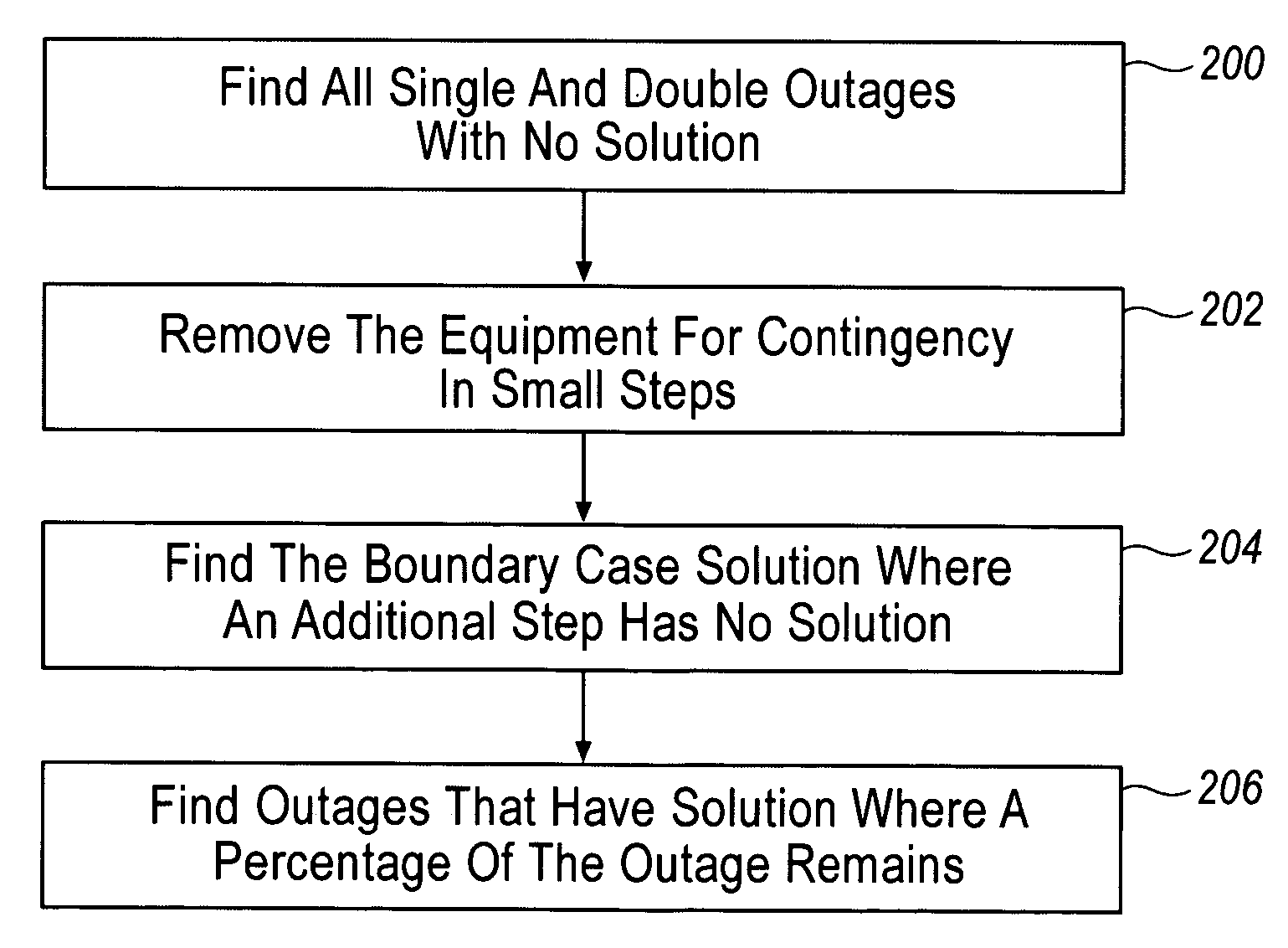
Referring now to the tables illustrated below, a hypothetical non-limiting example is illustrated that will use the agents as defined in Table 2 and diagrammed in FIG. 5 as well as a set of single contingencies that are defined by the letters A-F as discussed above. Each letter represents a single contingency or piece of electrical equipment that can be switched off and effectively removed from the electrical system. This example asserts that the (1) Voltage Collapse Diagnostic is performed as outlined in previous sections to obtain the agents from Table 2 and FIG. 5, (2) single contingency analysis is performed to find if any single outages cause voltage collapse and find those outages that are used to find the double outages that will be simulated, (2) double contingency analysis is performed for determining the set of double outages to be simulated by selecting X and N and by simulation of the resulting set of single outage combinations. A full discussion of this procedure is ou...
example 3
This hypothetical non-limiting example will also use the agents as defined in Table 2 and diagrammed in FIG. 5 as well as a set of single contingencies that are defined by the letters A-F. As in Example 2, each letter represents a single piece of electrical equipment that can be switched off and effectively removed from the electrical system. These single contingencies are intended to be a set independent of those in Example 2. This example asserts that the Voltage Collapse Diagnostic is performed as outlined in previous sections to obtain the agents from Table 2 and FIG. 5 and single contingency analysis is performed. From this single contingency analysis, it is determined that the single contingencies represented by the set A, C and E do not reach solutions to the load flow equations when the maximum percentage of the outage remaining in the system is equal to zero and are thus problematic single contingencies. Preventive Loadshedding Control is then performed on these single out...
PUM
 Abstract
Description
Claims
Application Information
 - R&D
- Intellectual Property
- Life Sciences
- Materials
- Tech Scout
- Unparalleled Data Quality
- Higher Quality Content
- 60% Fewer Hallucinations
Browse by: Latest US Patents, China's latest patents, Technical Efficacy Thesaurus, Application Domain, Technology Topic, Popular Technical Reports.
© 2025 PatSnap. All rights reserved.Legal|Privacy policy|Modern Slavery Act Transparency Statement|Sitemap|About US| Contact US: help@patsnap.com


