Dixon Techniques in spiral trajectories with off-resonance correction

a technology of offresonance correction and dixon technique, which is applied in the direction of diagnostic recording/measuring, instruments, and measurements using nmr, can solve the problems of severe geometric distortion, blurred artifacts in the reconstructed image, and artifacts in magnetic resonance imaging (mri)

Active Publication Date: 2005-02-10
CASE WESTERN RESERVE UNIV
View PDF17 Cites 27 Cited by
  • Summary
  • Abstract
  • Description
  • Claims
  • Application Information

AI Technical Summary

Problems solved by technology

Off-resonance effects (e.g., field inhomogeneity, susceptibility, chemical shift) cause artifacts in magnetic resonance imaging (MRI).
However, off-resonance artifacts sometimes appear as severe geometric distortion because of the relatively long readout time in echo planar imaging (EPI).
However, off-resonance effects cause blurring artifacts in the reconstructed image.
Most spiral off-resonance correction methods proposed to date are difficult to apply to correct for blurring artifacts due to the fat signals, since the fat-water frequency shift is typically much greater than that due to main magnetic field (B0) inhomogeneity across the field of view (FOV).
As such, off resonance artifacts remain one of the main disadvantages of spiral imaging.
Yet, SPSP pulses may not lead to satisfactory fat signal suppression in the presence of large B0 inhomogeneity.
Water and fat separation is unequivocal using this technique when magnetic field inhomogeneity is negligible over the scanned object.
However, when B0 inhomogeneity cannot be neglected, the original Dixon technique fails to accurately decompose water and fat signals.
The water-fat decomposition performance is almost equivalent to that of the 3PD technique, although off-resonance frequency estimation of this technique is unstable for voxels with nearly equal water and fat signal intensities.

Method used


Image

  • Dixon Techniques in spiral trajectories with off-resonance correction
  • Dixon Techniques in spiral trajectories with off-resonance correction
  • Dixon Techniques in spiral trajectories with off-resonance correction

Examples


examples

FIG. 6 shows the axial brain images. In FIG. 6, (a) and (b) are the water and fat images using the spiral 3PD technique, respectively. FIGS. 6(c) and 6(d) are the water and fat images using the spiral 2PD technique, respectively. FIG. 6(e) is one of the images directly reconstructed from the acquired data (TE 4.4 ms). FIG. 6(f) is the one of images reconstructed from the data with SPSP pulses (TE 7.5 ms) after off-resonance correction. FIG. 7 shows the axial pelvis images. In FIG. 7, (a)-(f) were acquired under the same conditions as those in corresponding locations in FIG. 6.

As observed in FIG. 6(e) and FIG. 7(e), the original images are affected by the high level of blurring artifacts for most of the imaged regions. However, as (a)-(d) in both FIGS. 6 and 7 show, these blurring artifacts are substantially reduced while unambiguous water-fat decomposition is achieved in both the spiral 3PD and 2PD techniques. FIG. 7(f) (SPSP pulses) shows that some fat signals in the right anteri...


PUM


Abstract

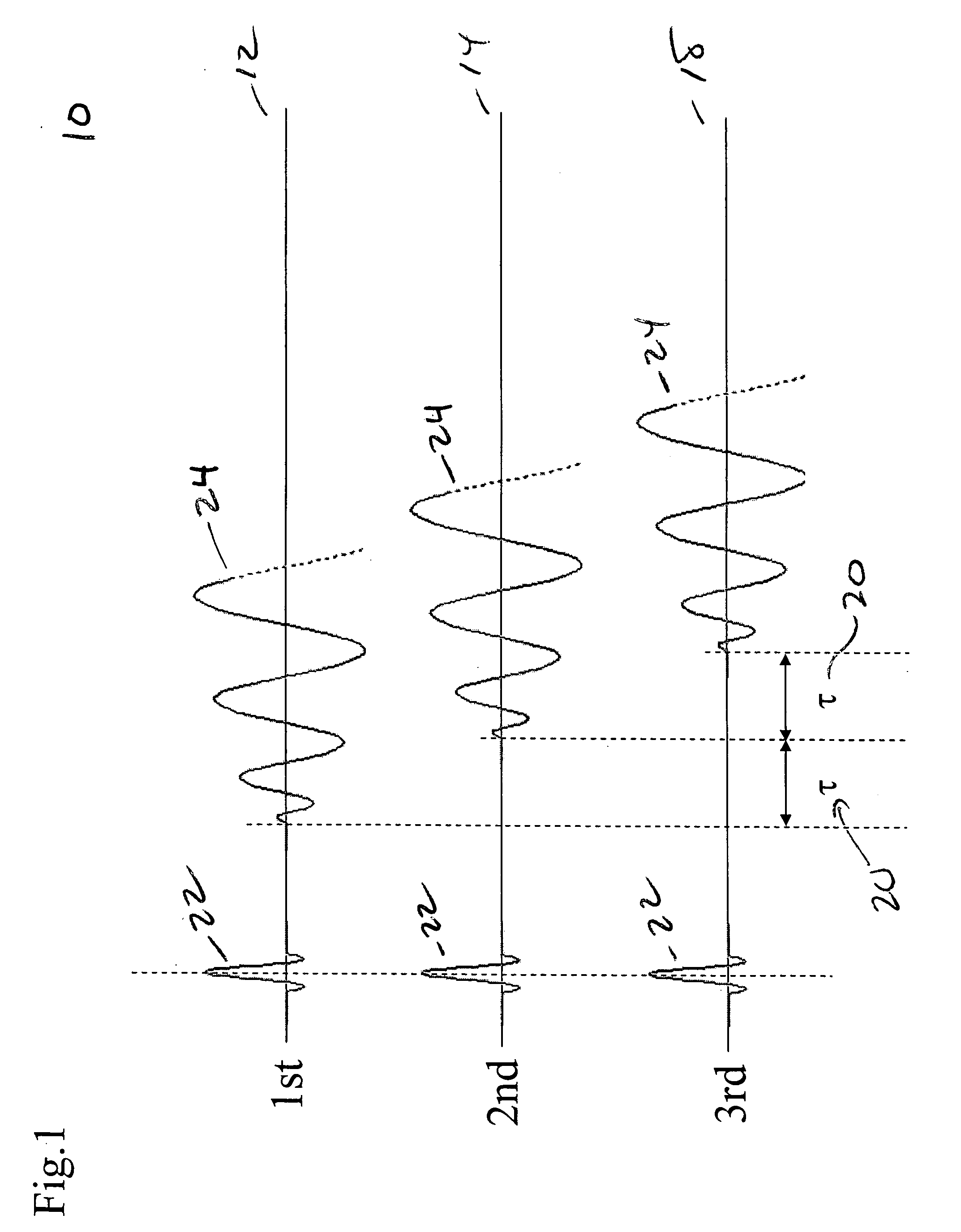
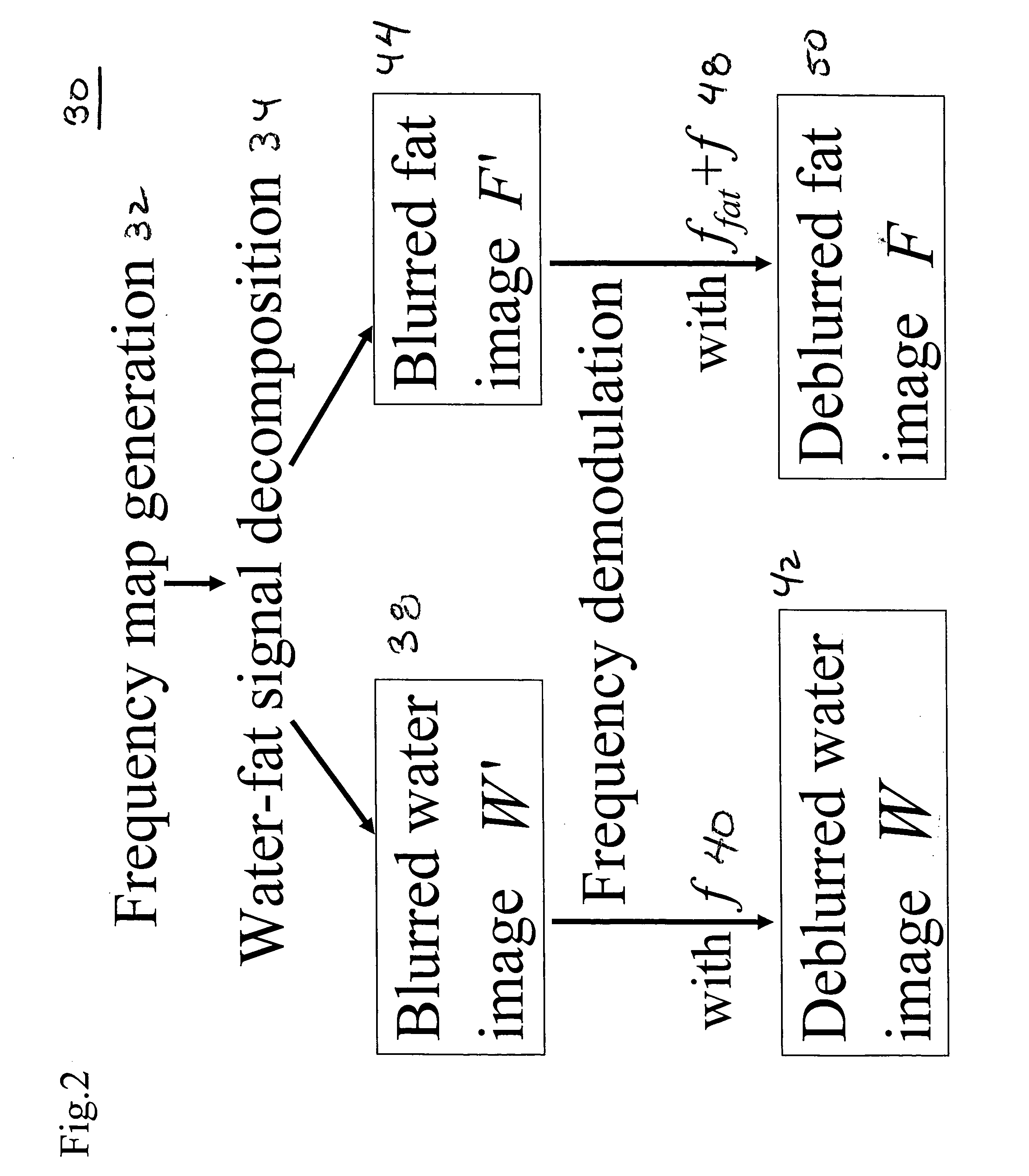
Spiral imaging has recently gained acceptance for rapid MR data acquisition. One of the main disadvantages of spiral imaging, however, is blurring artifacts due to off-resonance effects. Dixon techniques have been developed as methods of water-fat signal decomposition in rectilinear sampling schemes, and they can produce unequivocal water-fat signal decomposition even in the presence of B0 inhomogeneity. Three-point and two-point Dixon techniques can be extended to conventional spiral and variable-density spiral data acquisitions for unambiguous water-fat decomposition with off-resonance blurring correction. In the spiral three-point Dixon technique, water-fat signal decomposition and image deblurring are performed based on the frequency maps that are directly derived from the acquired images. In the spiral two-point Dixon technique, several predetermined frequencies are tested to create a frequency map. The techniques can achieve more effective and more uniform fat signal suppression when compared to the conventional spiral acquisition method with SPSP pulses.

Description

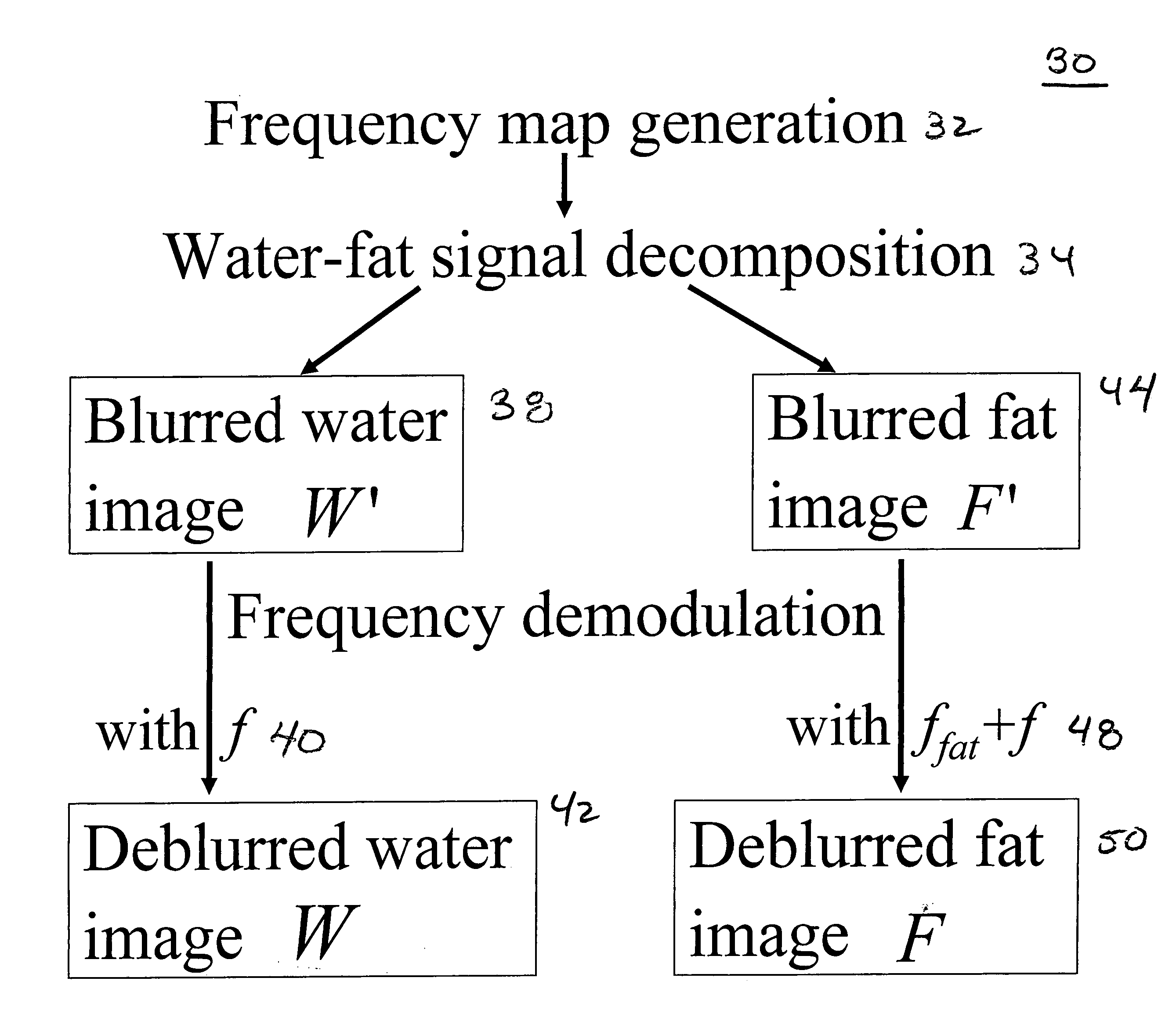
BACKGROUND Off-resonance effects (e.g., field inhomogeneity, susceptibility, chemical shift) cause artifacts in magnetic resonance imaging (MRI). The artifacts appear as positional shifts along the readout direction in rectilinearly sampled acquisitions. Usually, they are insignificant because of short readout times in normal spin-echo (SE) and gradient-echo (GRE) sequences. However, off-resonance artifacts sometimes appear as severe geometric distortion because of the relatively long readout time in echo planar imaging (EPI). Over the past decade, spiral imaging techniques have gained in popularity due to their short scan time and insensitivity to flow artifacts. However, off-resonance effects cause blurring artifacts in the reconstructed image. Most spiral off-resonance correction methods proposed to date are difficult to apply to correct for blurring artifacts due to the fat signals, since the fat-water frequency shift is typically much greater than that due to main magnetic fi...

Claims


Application Information

Patent Timeline
Patent Type & Authority Applications(United States)
IPC IPC(8): G01R33/54G01R33/565
CPCG01R33/4828G01R33/56563G01R33/565
Inventor MORIGUCHI, HISAMOTOLEWIN, JONATHAN S.DUERK, JEFFREY L.
Owner CASE WESTERN RESERVE UNIV
Why Eureka
Try Eureka