
Excavation teaching apparatus for construction machine

a construction machine and teaching device technology, applied in the direction of vehicle position/course/altitude control, process and machine control, instruments, etc., can solve the problems of difficult alignment work, work is complicated, and work is very troublesome, so as to increase the working efficiency during excavation and facilitate confirmation. , the effect of easy confirmation

Inactive Publication Date: 2005-02-03
NIHON KENKI CO LTD
View PDF9 Cites 128 Cited by
  • Summary
  • Abstract
  • Description
  • Claims
  • Application Information

AI Technical Summary

Benefits of technology

[0009] A first object of the present invention is to provide an excavation teaching device for a construction machine, which can overcome the above-mentioned first and second problems, and which can realize easy confirmation of a proper target excavation surface and increase the working efficiency during excavation even in work of forming the face of slope in complicated three-dimensional landforms.
[0010] A second object of the present invention is to provide an excavation teaching device for a construction machine, which can overcome the above-mentioned first and third problems, and which can realize easy confirmation of a proper target excavation surface, facilitate positioning of a machine body during excavation, and increase the working efficiency even in work of forming the face of slope in complicated three-dimensional landforms.
[0014] Thus, one of the plurality of small plane surfaces constituting the three-dimensional target landform, which satisfies that the direction normal to the one small plane surface is parallel within the range of allowable error to the plane in which the operating mechanism operates, is discriminatively displayed as the target excavation surface. Even in complicated three-dimensional landforms where the landform along which excavation is to be performed changes with movement of the construction machine, therefore, the operator can easily confirm the target excavation surface corresponding to the current position of the construction machine, and hence the working efficiency during excavation can be increased.
[0026] Thus, the projected line of the line normal to the target excavation surface and the direction in which the operating mechanism of the construction machine operates with current orientation thereof are displayed on the same screen. Even in complicated three-dimensional landforms where the landform along which excavation is to be performed changes with movement of the construction machine, therefore, the operator can intuitively easily confirm the position of the construction machine suitable for excavation to follow the target excavation surface, and hence the working efficiency during excavation can be increased.

Problems solved by technology

That necessity has invited a first problem that the work is further complicated.
However, this aligning work is required each time the target excavation surface is set.
In particular, when a plurality of small plane surfaces are present in a small area, the operator must eventually teach all of those small plane surfaces, thus resulting in a second problem that the work is very troublesome.
However, there is no concrete guide indicating in which direction the machine body is to be operated in practice, and hence the direction in which the machine body is to be operated must be judged at the operator's discretion at the time of starting the operation.
That necessity has invited a third problem that an unskilled operator cannot easily position the machine body in proper orientation.

Method used


Image

  • Excavation teaching apparatus for construction machine
  • Excavation teaching apparatus for construction machine
  • Excavation teaching apparatus for construction machine

Examples


Embodiment Construction

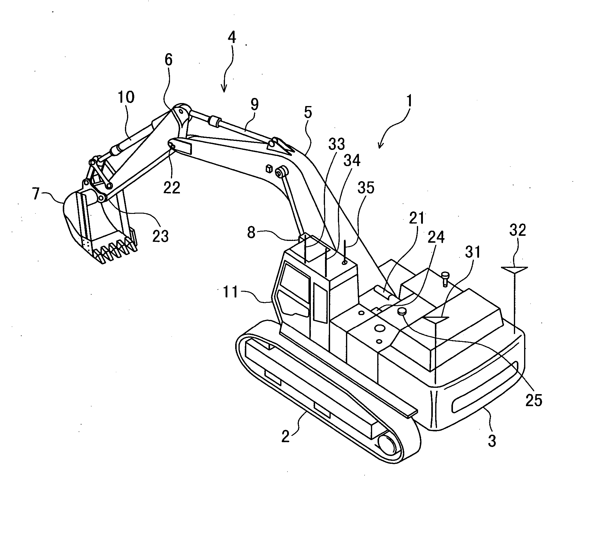
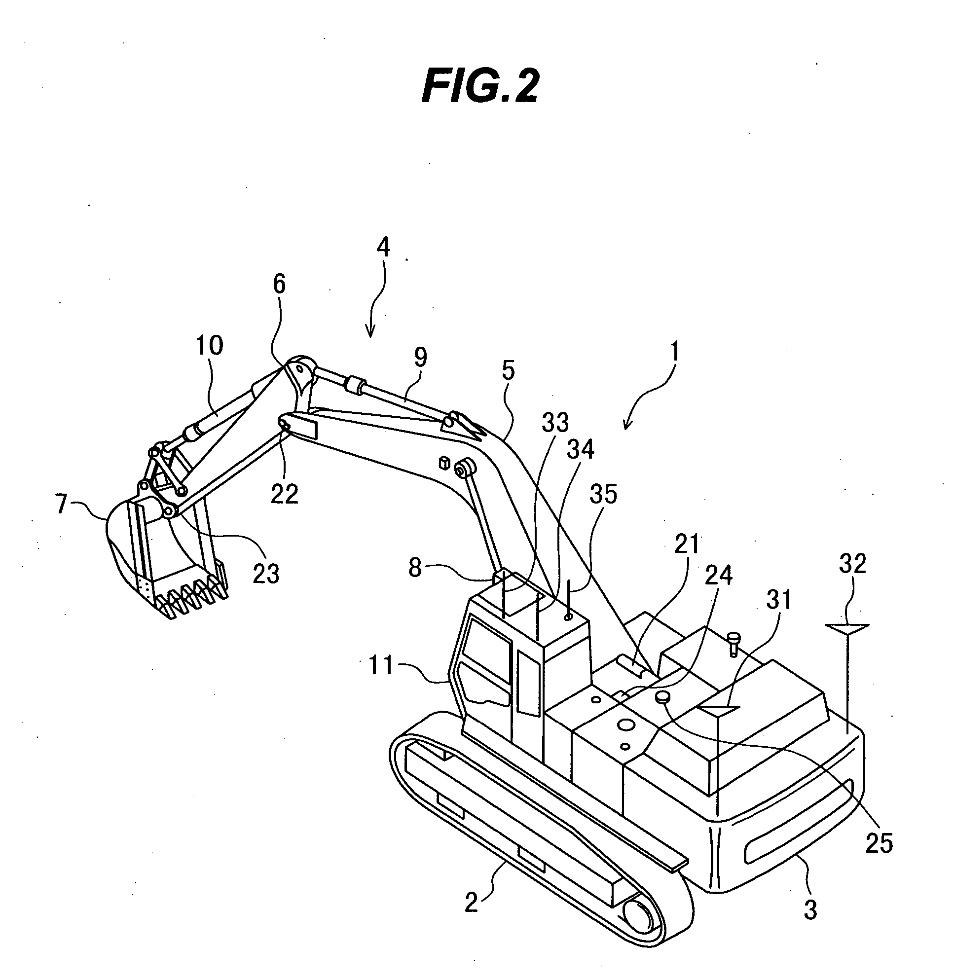
[0051] With reference to FIGS. 1 to 13, a description will be made below of the case in which an excavation teaching device for a construction machine according to one embodiment of the present invention is applied to a hydraulic excavator.

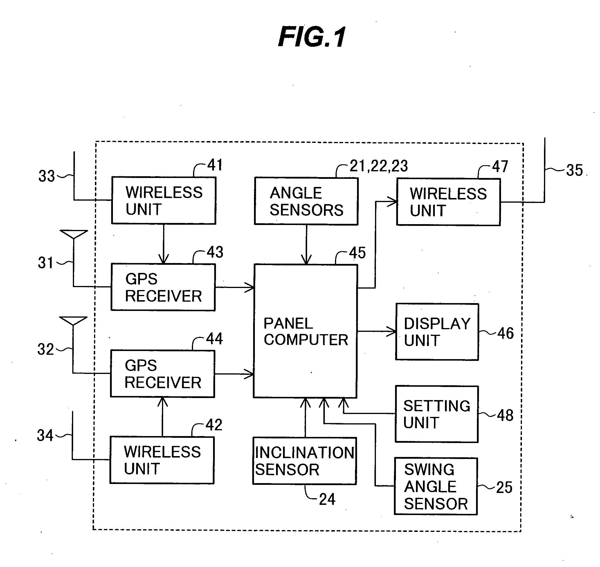
[0052]FIG. 1 is a block diagram showing the configuration of a work position measuring system employing an excavation teaching device for a construction machine according to one embodiment of the present invention.

[0053] The work position measuring system comprises wireless units 41, 42 for receiving reference data (described later) from a reference station via antennas 33, 34; GPS receivers 43, 44 for measuring respective three-dimensional positions of GPS antennas 31, 32 in real time based on the reference data received by the wireless units 41, 42 and a signal from a GPS satellite received by each of the GPS antennas 31, 32; a panel computer 45 for computing the position of a fore end (monitoring point) of a bucket 7 of a hydraulic excavator ...


PUM


Abstract

The invention is intended to provide an excavation teaching device for a construction machine which can realize easy confirmation of a proper target excavation surface and increase the working efficiency during excavation even in work of forming the face of slope in complicated three-dimensional landforms. A display unit (46) displays, as an image in a first screen area (46a), a plurality of small plane surfaces G constituting a three-dimensional target landform and illustrations of a body S of the construction machine and a bucket B as an excavating tool at a fore end of an operating mechanism. Also, the display unit discriminatively displays in the first screen area, as a target excavation surface TG defined by a small plane surface along which excavation is feasible, one of the plurality of small plane surfaces constituting the three-dimensional target landform, which satisfies that the direction normal to the one small plane surface is parallel within a range of allowable error to a plane in which the operating mechanism operates. A panel computer (45) displays, on the display unit (46), a line resulting from projecting a line normal to the target excavation surface, selected from among the plurality of, small plane surfaces constituting the three-dimensional target landform, and the direction in which the operating mechanism of the construction machine operates with current orientation thereof, as well as relative positional relationships among the body of the construction machine, the position of the operating mechanism and the target landform.

Description

TECHNICAL FIELD [0001] The present invention relates to an excavation teaching device for a construction machine, such as a hydraulic excavator. More particularly, the present invention relates to an excavation teaching device for a construction machine, which is suitable for teaching a target excavating position when excavation is to be performed on a three-dimensional target landform by using an operating mechanism for excavation, such as a bucket. BACKGROUND ART [0002] When constructing roads in slants in a mountain region, etc., earth moving work, such as cutting and filling-up, is first carried out to form a necessary foundation by using a construction machine, such as a hydraulic excavator and a bulldozer, and the face of slope is then formed around the foundation by using the hydraulic excavator, etc. to prevent breaking of the ground. This slope-face forming is highly accurate excavation and shaping work and requires skills. Particularly, if the earth is excessively excavate...

Claims


Application Information

Patent Timeline
IPC IPC(8): E02F9/20E02F9/26
CPCE02F9/2045E02F9/265E02F9/262E02F9/205
Inventor FUJISHIMA, KAZUOISHIBASHI, HIDETO
Owner NIHON KENKI CO LTD
Learn More