Expansion apparatus

Active Publication Date: 2005-01-27
WEATHERFORD TECH HLDG LLC
View PDF5 Cites 10 Cited by
  • Summary
  • Abstract
  • Description
  • Claims
  • Application Information

AI Technical Summary

Benefits of technology

[0013] The ability to selectively deploy expansion members at different times may provide the advantage of extending the operational life of the expansion apparatus, by permitting the deployment of the expansion members to be staged such that, for example, a number of expansion members, each with a limited life-span, may be deployed one after the other, such that the life-span of the apparatus is equivalent to the total life-spans of the individual expansion members. Thus, an expansion apparatus in accordance with an embodiment of the present invention may be capable of expanding a greater length of tubular in a single run, compared to that of conventional tools, and therefore reduce the amount of time spent running expansion apparatus into and out of the tubular and reduce the time required to expand the tubular.
[0024] Preferably, the expansion apparatus is adapted such that only one expansion member, or one set of expansion members, can be deployed at a time. This reduces the forces or torque required to rotate or otherwise operate the expansion apparatus and further prevents redundant cold working of the tubular, which can lead to unplanned wall thinning of the tubular.
[0051] Applicant has found that during operation of certain expansion devices, and in particular in certain rotary expansion devices and most particularly compliant rotary expansion devices, there is inherently a lead member in a set of expansion members, and this lead member is subjected to the greatest forces in the set and therefore typically experiences the greatest rate of wear. Manipulating an expansion member in the set enables the lead member to be switched during operation of the expansion device. This provides the advantage of being able to equalise the wear experienced and thus extend the operational life of the set of expansion members, and in turn the operational life of the expansion device.

Problems solved by technology

One difficulty experienced with known rotary expansion tools is the limited length of tubing that can be expanded by the expansion tool before the tool has to be replaced: this is due to a number of factors, including wear of the rollers and in particular the relatively short life of the roller bearings.

Method used


Image

  • Expansion apparatus
  • Expansion apparatus
  • Expansion apparatus

Examples


Embodiment Construction

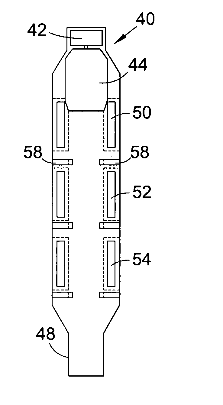
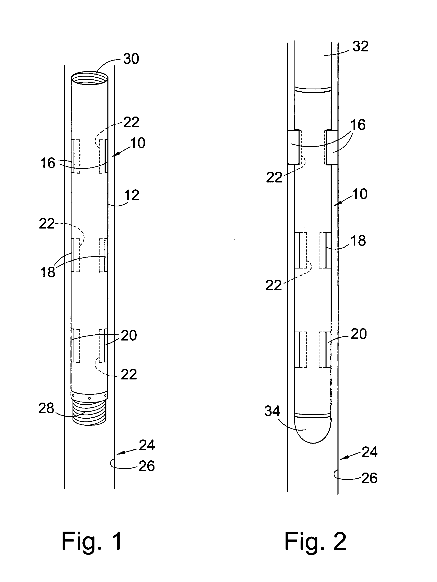
[0074] Referring initially to FIG. 1 of the drawings, there is illustrated a side view of an expansion apparatus in accordance with one embodiment of the present invention, indicated generally by reference numeral 10. The expansion apparatus 10 comprises a body 12, which is generally tubular and has a number of sets of expansion members 16, 18, 20 spaced along the length of the apparatus 10. Each individual expansion member 16, 18, 20 is located in a respective body recess 22 from which the expansion member 16, 18, 20 can be radially deployed.

[0075] In a first configuration, as illustrated in FIG. 1, the expansion members 16, 18, 20 are retracted such that the expansion apparatus 10 defines a diameter smaller than that of a tubular 24 to be expanded, thus allowing the expansion apparatus 10 to be run into the tubular 24. Once the expansion apparatus 10 is located within the tubular 24, the expansion members 16, 18, 20 can be selectively deployed, as will be described hereinafter, s...


PUM


Abstract

An expansion apparatus for expanding a portion of a tubular comprises at least two expansion members adapted for selective deployment against a wall of a tubular. The expansion apparatus may be controlled to select a first expansion member to be deployed and the apparatus operated to expand a section of the tubular. The deployed expansion member may then be inactivated or retracted, such that the expansion member is no longer deployed against the wall of the tubular or is otherwise rendered inoperative, and a second expansion member can then be deployed and a further section of the tubular expanded.

Description

CROSS-REFERENCE TO RELATED APPLICATIONS [0001] This application claims benefit of Great Britain patent application serial number GB 0316048.8, filed Jul. 9, 2003, which is herein incorporated by reference. BACKGROUND OF THE INVENTION [0002] 1. Field of the Invention [0003] The present invention relates to an apparatus for the expansion of tubulars, and in particular to an apparatus for expanding tubulars utilised in the oil and gas industry. [0004] 2. Description of the Related Art [0005] Recent developments in the fields of exploration and production of hydrocarbons have led to the introduction of technology that enables the expansion of sections of tubing downhole. The tubing may take a number of forms including: casing, liner, sandscreens, packers and hangers. A variety of expansion tools and methods are known, and include the use of expansion mandrels. The expansion mandrel may be in the shape of a cone and may be forced through a section of tubing by the application of an appro...

Claims


Application Information

Patent Timeline
IPC IPC(8): E21B43/10
CPCE21B43/105
Inventor METCALFE, PAUL DAVIDHARRALL, SIMON JOHNELLINGTON, PETER
Owner WEATHERFORD TECH HLDG LLC
Why Eureka
Try Eureka