Method and system for wireless communication networks using relaying

Inactive Publication Date: 2005-01-20
TELEFON AB LM ERICSSON (PUBL)
View PDF10 Cites 318 Cited by
  • Summary
  • Abstract
  • Description
  • Claims
  • Application Information

AI Technical Summary

Benefits of technology

Thanks to the invention it is possible to better adjust the forwarding on the second link to the actual conditions present during a communication session. In addition the forwarding can be better adjusted to changes in the conditions.
One advantage afforded by the present invention is that the more precise and reliable characterization of the individual radio paths may be used to determine and optimize different transmission parameters. Whereby, the capabilities of a cooperative relaying network, for example, may be more fully exploited.
A further advantage is that characterisation of the first and second link advantageously is performed in the relay stations. Hence, the method according to the invention fascilitates a distribution of functionalities in the network allowing an increase in the number of relay stations in a communication session without any significant increase in the amount of protocol overhead that is needed for the transmission of data from the transmitter to the receiver.
A yet further advantage further advantage of the method and system according to the present invention is that the improved characterization of the first and second link facilitate to take full advantage of the anticipated advantages of a network with cooperative relaying that comprises a larger number of relaying stations. With the invention used in a coherent combining setting, the directivity gain and diversity gain increases with increasing number of relay stations. The directivity gain itself offers increased SNR that can be used for range extension and / or data rate enhancement. The diversity gain, increases the robustness of the communication, providing a more uniform communication quality over time. While directivity and diversity gain can be provided by various traditional advanced antenna solutions, where the antennas are placed either at the transmitter or the receiver, the proposed solution is generally not limited to the physical space constraints as is seen in basestations or mobile terminals. Hence, there is indeed a potential to use a larger number of relays, than the number of antennas at a basestation or a mobile station, and hence offer even greater directivity and diversity gains.

Problems solved by technology

This has the consequence that performance may degrade and resources are inefficiently utilized.
Whereby, the prior art has not been able to fully take advantage of the anticipated advantages of a cooperative relaying network.

Method used


Image

  • Method and system for wireless communication networks using relaying
  • Method and system for wireless communication networks using relaying
  • Method and system for wireless communication networks using relaying

Examples


Embodiment Construction

Embodiments of the invention will now be described with reference to the figures.

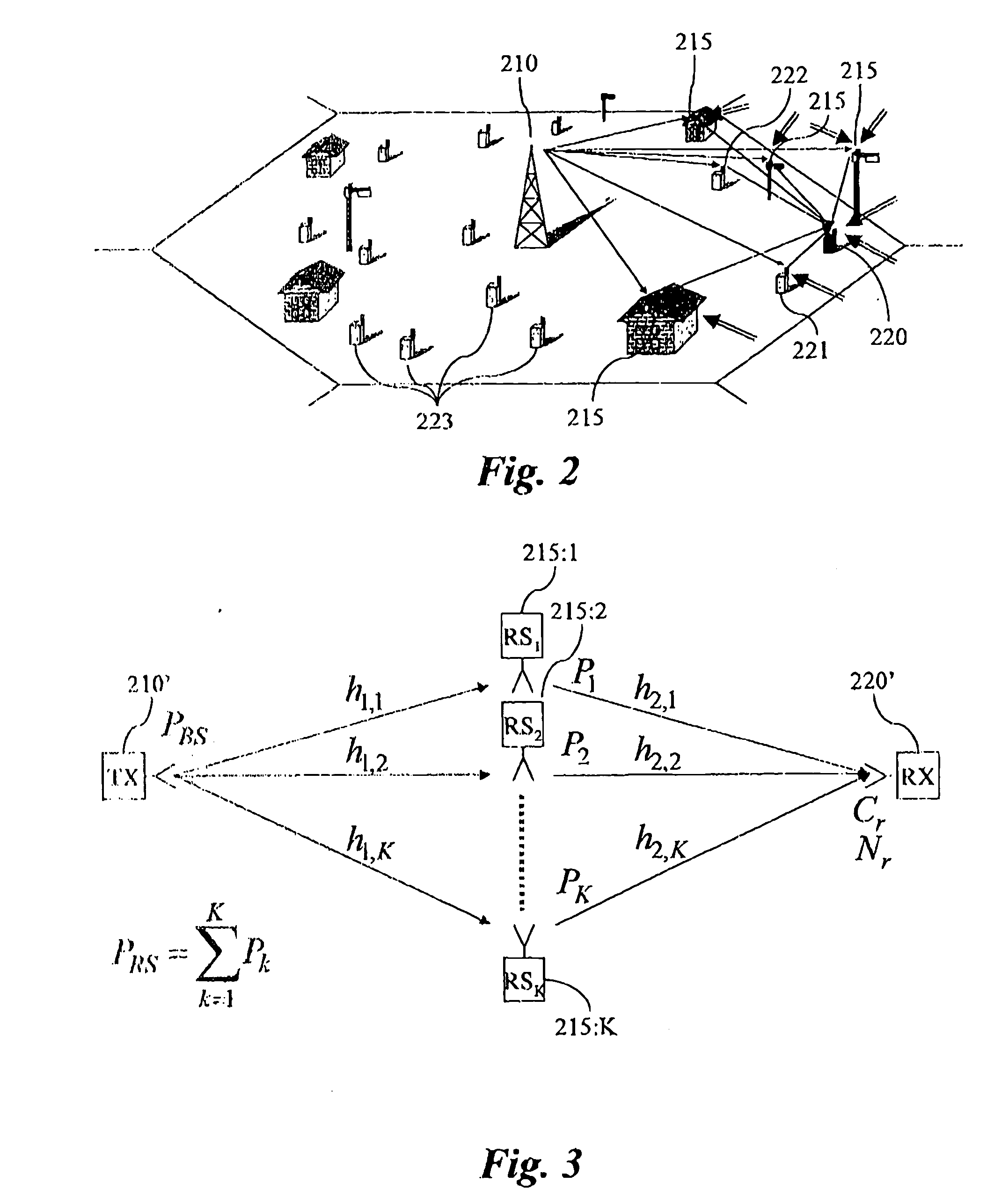
The network outlined in FIG. 2 is an example of a cooperative relaying network wherein the present invention advantageously is implemented. The figure shows one cell 205 of the wireless network comprising a basestation 210 (BS), a plurality of relay stations 215 (RS) and a plurality of mobile stations (MS) 220-223. As shown in the figure, the relay stations 215 are mounted on masts, but may also be mounted on buildings, for example. Fixed relays may be used as line of sight conditions can be arranged, directional antennas towards the basestation may be used in order to improve SNR (Signal-to-Noise Ratio) or interference suppression and the fixed relay may not be severely limited in transmit power as the electricity supply network typically may be utilized. However, mobile relays, such as users mobile terminals, may also be used, either as a complement to fixed relays or independently. The mobile stat...


PUM


Abstract

The present invention relates to wireless networks using relaying. In the method according to the present invention of performing communication in a two-hop wireless communication network, a transmitter 210, a receiver 220 and at least one relay station 215 are engaged in a communication session. The relay station 215 forwards signals from a first link between the transmitter 210 and the relay station 215 to a second link between the relay stations 215 and the receiver 220. The forwarding performed by the at least one relay station 215 is adapted as a response to estimated radio channel characteristics of at least the first link. Preferably the forwarding is adapted as a response to estimated radio channel characteristics of both the first and second link.

Description

FIELD OF THE INVENTION The present invention relates to relay supported wireless communication to enhance communication performance. In particular the invention relates to a method and a system for performing communication in a two-hop wireless communication network. BACKGROUND OF THE INVENTION A main striving force in the development of wireless / cellular communication networks and systems is to provide, apart from many other aspects, increased coverage or support of higher data rate, or a combination of both. At the same time, the cost aspect of building and maintaining the system is of great importance and is expected to become even more so in the future. As data rates and / or communication distances are increased, the problem of increased battery consumption is another area of concern. Until recently the main topology of wireless networks has been fairly unchanged, including the three existing generations of cellular networks. The topology characterized by the cellular architec...

Claims


Application Information

Patent Timeline
IPC IPC(8): H04B7/005H04B7/02H04B7/14H04B7/15H04B7/155H04B15/00H04L1/00H04L1/06H04L25/02H04L25/20H04L25/52H04L27/26H04W52/46H04W88/02
CPCH04B7/022H04W88/02H04B7/15528H04B7/15592H04B7/2606H04L1/0001H04L1/0021H04L1/0618H04L5/0007H04L5/0035H04L5/0048H04L25/0206H04L25/0224H04L25/20H04L27/2602H04L27/2655H04L2001/0097H04W52/40H04W52/46H04B7/026H04L25/0204H04W84/08H04W16/26H04B7/14H04W48/10
Inventor LARSSON, PETER
Owner TELEFON AB LM ERICSSON (PUBL)
Why Eureka
Try Eureka