
Lamp with a capability of concentrating light

a technology of concentrating light and lamp, which is applied in the field of lamps, can solve the problems of insufficient illumination and dispersion of light, and achieve the effect of increasing the brightness of the light emitted by the lamp

Inactive Publication Date: 2005-01-20
YEH PETER
View PDF4 Cites 70 Cited by
  • Summary
  • Abstract
  • Description
  • Claims
  • Application Information

AI Technical Summary

Benefits of technology

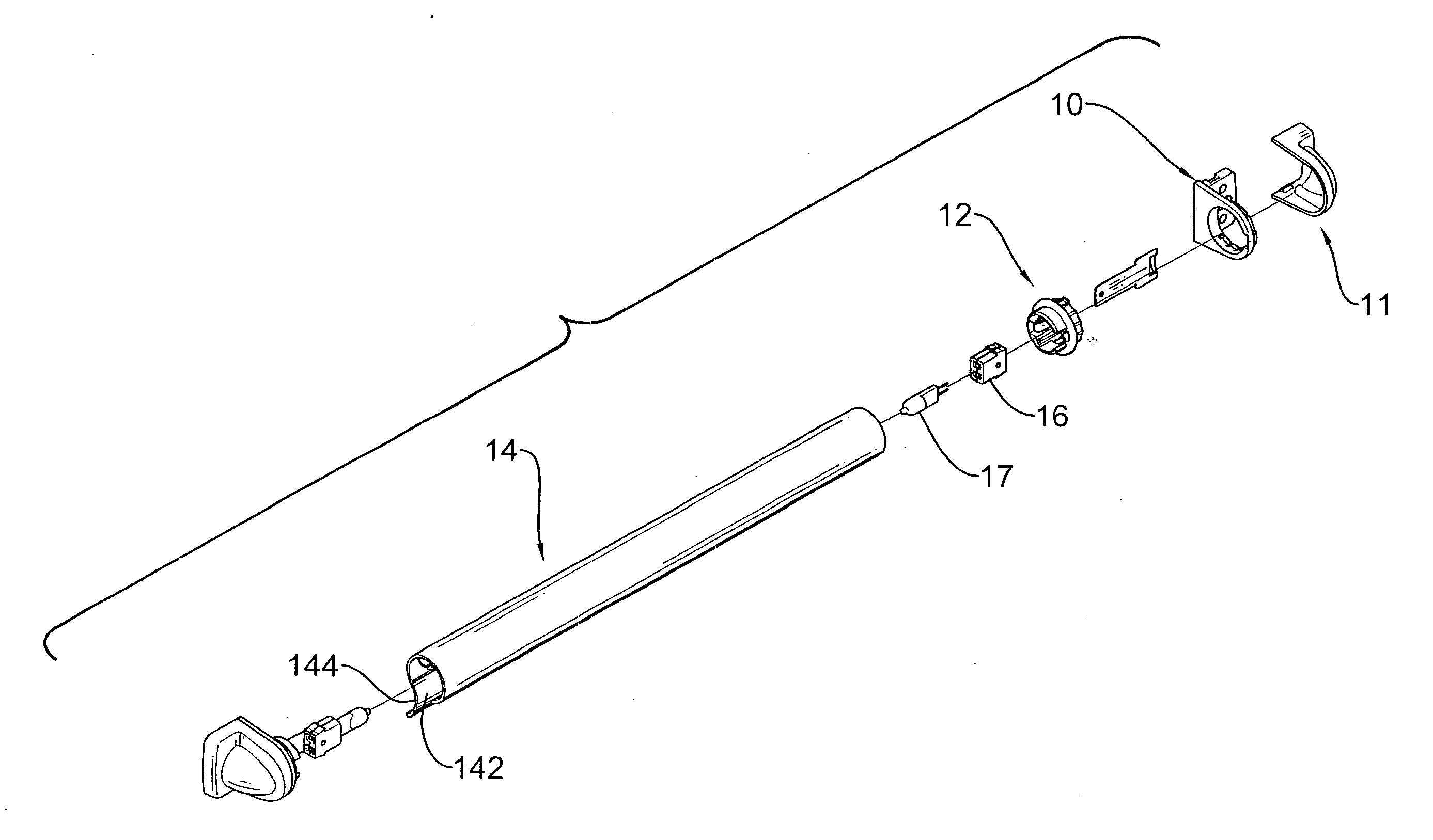
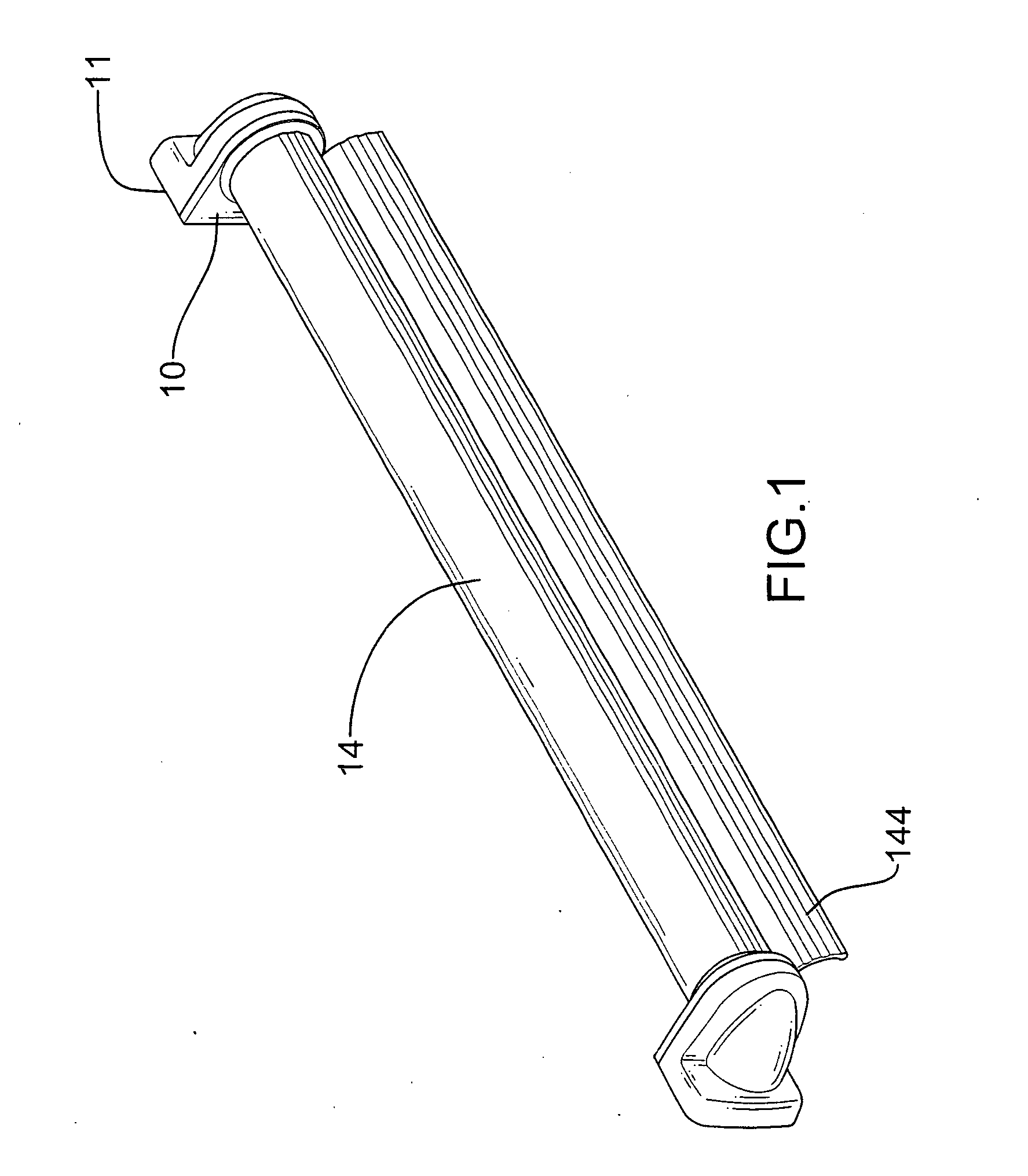
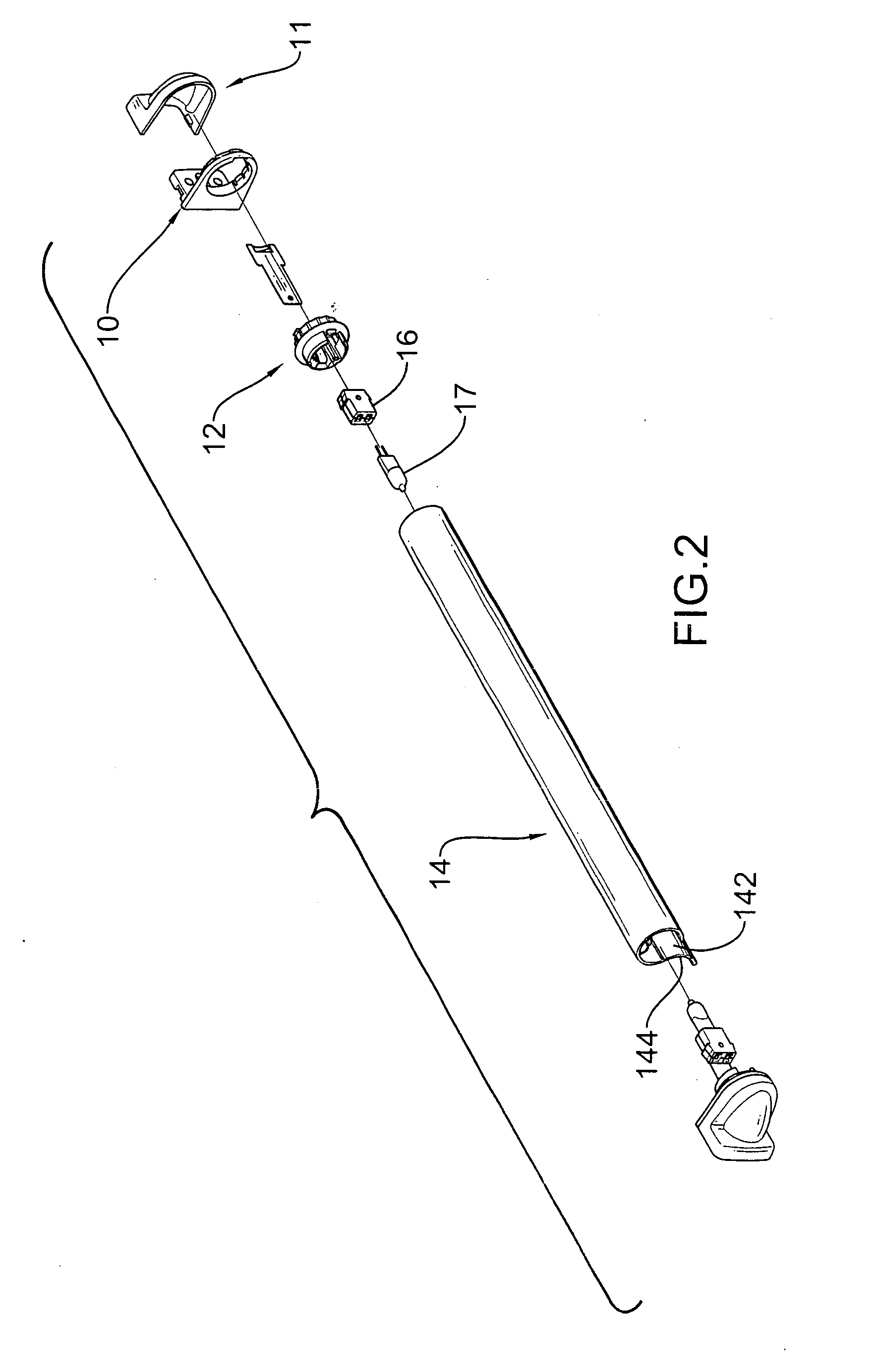
[0008] The lamp has two brackets, two shade holders, a shade, two sockets and two illuminating elements. The shade holders are attached respectively to the brackets. The shade is mounted between the shade holders and has a tubular body, a slit and an extension. The tubular body is made of an opaque material and has an axis and two open ends attached respectively to the shade holders. The slit is longitudinally defined through the tubular body along the axis. The extension extends from the tubular body along the slit. The sockets are mounted respectively on the shade holders. The illuminating elements are attached to the sockets and are mounted in the open ends of the tubular body of the shade. In such an arrangement, light emitted from the illuminating elements is concentrated and emits only from the slit in the shade. Accordingly, the brightness of the light emitted from the lamp is increased.

Problems solved by technology

However, because the shade of a conventional lamp is made of a material pervious to light, the light will disperse when it passes through the shade.
The light emitted from a conventional lamp is not concentrated so the illumination provided by a conventional lamp is not bright enough.

Method used


Image

  • Lamp with a capability of concentrating light
  • Lamp with a capability of concentrating light
  • Lamp with a capability of concentrating light

Examples


Embodiment Construction

[0015] With reference to FIGS. 1 to 3, a lamp in accordance with the present invention comprises two brackets (10), two shade holders (12), a shade (14), two sockets (16), two illuminating elements (17) and optionally two end caps (11). Each bracket (10) is L-shaped and has a first side (not numbered) and a second side (not numbered) with a mounting hole (106). The first side of each respective bracket (10) has multiple through holes (102). Multiple fasteners (not shown) respectively penetrate the through holes (102) to secure the bracket (10) to an object such as a wall, a ceiling of a vehicle or a backrest of a seat. The mounting hole (106) is defined through the second side of each bracket (10).

[0016] The shade holders (12) are attached respectively to the brackets (10). Each shade holder (12) has a distal end (not numbered) and a proximal end (not numbered). The proximal ends of the shade holders (12) are inserted respectively into the mounting holes (106) in the brackets (10)....


PUM

PropertyMeasurementUnit
outer diameteraaaaaaaaaa
inner diameteraaaaaaaaaa
brightnessaaaaaaaaaa

Abstract

A lamp that can concentrate light has two brackets, two shade holders, a shade, two sockets and two illuminating elements. The shade holders are attached respectively to the brackets. The shade is mounted between the shade holders and has a tubular body, a slit and an extension. The tubular body is made of an opaque material and is attached to the shade holders. The slit is longitudinally defined through the tubular body. The extension extends from the tubular body along the slit. The sockets are respectively mounted on the shade holders. The illuminating elements are attached to the sockets and are mounted in the open ends of the tubular body of the shade. Accordingly, the light emitting from the illuminating elements is concentrated and emits only from the slit in the shade to increase the brightness of the light emitted from the lamp.

Description

BACKGROUND OF THE INVENTION [0001] 1. Field of the Invention [0002] The present invention relates to a lamp, and more particularly to a lamp that can concentrate light to enhance the brightness provided by the lamp. [0003] 2. Description of Related Art [0004] A lamp is usually mounted on a wall or an object, such as a backrest of a seat or a ceiling in a vehicle or an airplane to provide illumination for a user. A conventional lamp in accordance with the prior art substantially comprises a base, an illuminating element and a shade. The illuminating element is mounted on the base and is electrically connected to a power source. The shade is mounted on the base and is mounted around the illuminating element. The shade is made of a material pervious to light emitting from the illuminating element. [0005] However, because the shade of a conventional lamp is made of a material pervious to light, the light will disperse when it passes through the shade. The light emitted from a convention...

Claims


Application Information

Patent Timeline
Patent Type & Authority Applications(United States)
IPC IPC(8): B60Q3/02F21S8/00F21S8/04F21V11/12F21V14/08F21V17/06
CPCF21S8/033F21S8/04F21V11/12F21V14/08F21V17/06F21Y2115/10B60Q3/76
Inventor YEH, PETER
Owner YEH PETER
Learn More