
Coil component and fabricaiton method of the same

a technology of coil components and fabrication methods, applied in the direction of transformers/inductances, magnetic cores, magnetic bodies, etc., can solve the problems of coil components, range has a possibility of undesired vibration, coil components of jp, etc., and achieve the effect of suppressing the whine of coil components driven

Active Publication Date: 2005-01-20
DENSO CORP 50 INTEREST +2
View PDF15 Cites 76 Cited by
  • Summary
  • Abstract
  • Description
  • Claims
  • Application Information

AI Technical Summary

Benefits of technology

[0009] It is an object of the present invention to provide a coil component which has a property of high withstand voltage and another property of resistance to undesired pulses and can suppress the whine of the coil component driven even at the audible frequency, and to provide a fabrication method thereof.

Problems solved by technology

The driving frequency of the audibility range has a possibility of undesired vibration which is caused by mutual forces of attraction between coil wires or between a coil and a magnetic core.
In addition, if the coil component has an air-gap, the coil component further has a possibility of undesired vibration caused by mutual forces of attraction between portions of the core which is provided with the air-gap.
Thus, it is conceivable that the coil component of JP-A 2001-185421 is not suitable for the high-power and low-frequency system.

Method used


Image

  • Coil component and fabricaiton method of the same
  • Coil component and fabricaiton method of the same
  • Coil component and fabricaiton method of the same

Examples


Embodiment Construction

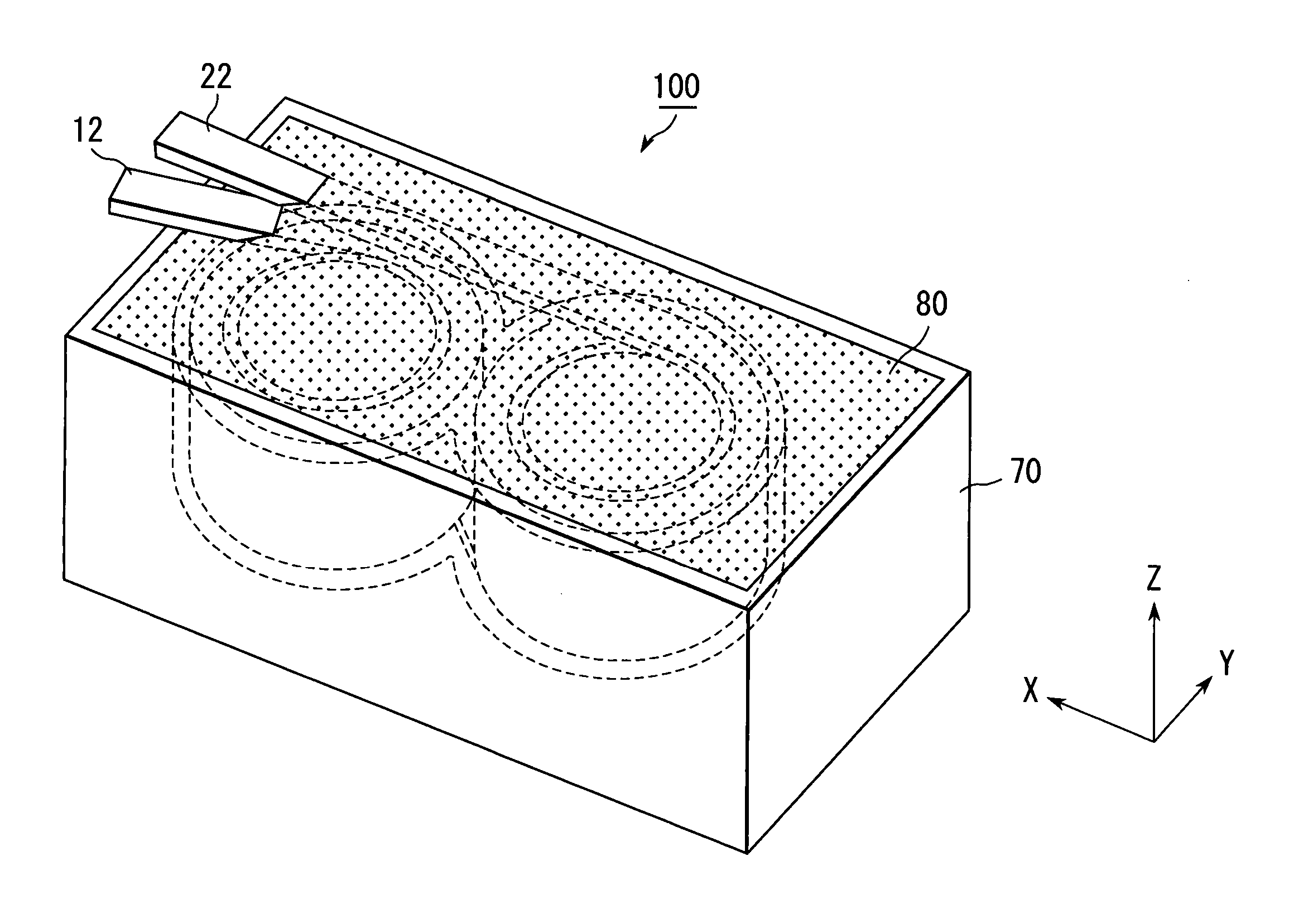
[0034] With reference to FIGS. 1 to 10, a coil component 100 according to a first embodiment of the present invention comprises a coil-containing insulator enclosure 60 and a magnetic core 80. In this embodiment, the coil-containing insulator enclosure 60 is completely embedded in the magnetic core 80.

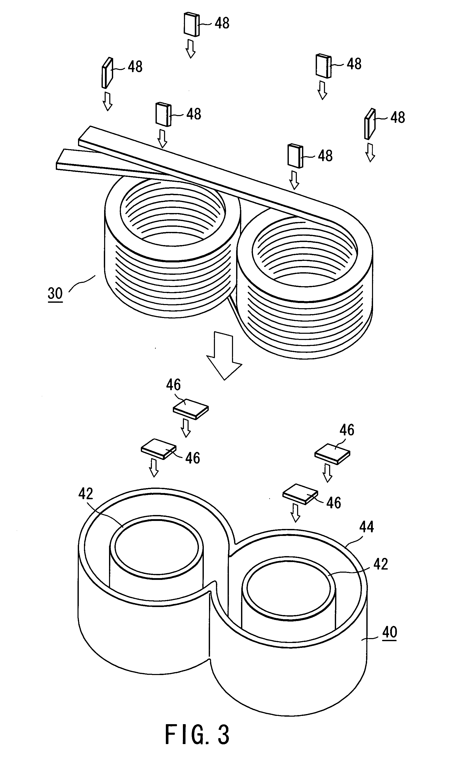
[0035] As shown in FIGS. 4 to 6, the coil-containing insulator enclosure 60 has a structure obtainable by enclosing a coil 30 with an insulator 50, except for end portions 12, 22 of the coil 30.

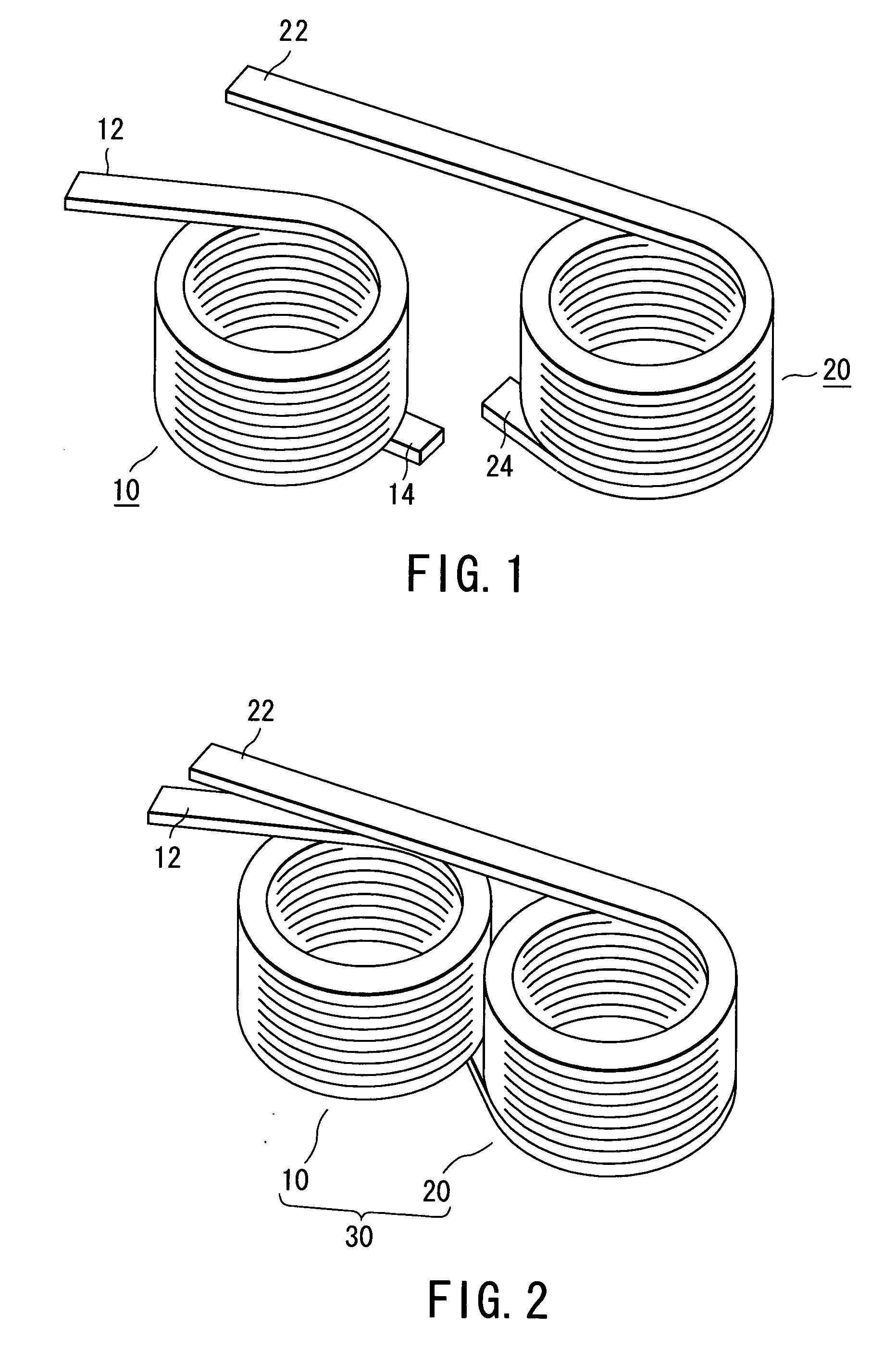
[0036] As seen from FIGS. 1 and 2, the coil 30 of the present embodiment has a spectacles- or glasses-shaped structure or a figure eight structure which is obtained by connecting two coil members 10, 20. Each of the coil members 10, 20 is an edgewise-wound coil obtainable by winding a flat type wire edgewise. The coil member 10 has two end portions 12, 14. Likewise, the coil member 20 has two end portions 22, 24. The coil 30 is obtained by connecting the end portions 14, 24 of the coil members...


PUM

PropertyMeasurementUnit
diameteraaaaaaaaaa
elastic modulusaaaaaaaaaa

Abstract

A coil component (100) comprises a coil-containing insulator enclosure and a magnetic core (80). The coil-containing insulator enclosure can be obtained by enclosing a coil (30), except for end portions (12, 22) of the coil (30), with an insulator (50), wherein the insulator (50) comprises at least first resin. The magnetic core (80) is made of a mixture of a second resin (82) and powder, which comprises at least magnetic powder (84). The coil-containing insulator enclosure is embedded in the magnetic core (80).

Description

BACKGROUND OF THE INVENTION [0001] This invention relates to a coil component and the fabrication method thereof. In particular, this invention relates to the coil component which is used as a reactor in a high-power system such as an energy control of a battery mounted on an electrically-powered car or a hybrid car including an electromotor and an internal-combustion engine. [0002] In an electrically-powered car or a hybrid car, the coil component is driven at frequencies within the audibility range of the human ear. Specifically, the normal driving frequency of the coil component in the electrically-powered car or the hybrid car belongs to a frequency range of from several kilohertz to several tens kilohertz. [0003] The driving frequency of the audibility range has a possibility of undesired vibration which is caused by mutual forces of attraction between coil wires or between a coil and a magnetic core. The undesired vibration makes an audible noise or whine. In addition, if the ...

Claims


Application Information

Patent Timeline
Patent Type & Authority Applications(United States)
IPC IPC(8): H01F1/147H01F1/153H01F1/24H01F3/08H01F17/06H01F41/00H01F41/02
CPCH01F1/1475H01F1/15366H01F1/24H01F3/08H01F2017/048H01F41/005H01F41/0246H01F2017/046H01F17/062H01F27/24
Inventor ONO, KAZUYUKIYANBE, TAKASHIMATSUMOTO, HATSUO
Owner DENSO CORP 50 INTEREST
Learn More