Arrangement and method for audio source tracking

Active Publication Date: 2005-01-13
CISCO TECH INC
View PDF10 Cites 75 Cited by
  • Summary
  • Abstract
  • Description
  • Claims
  • Application Information

AI Technical Summary

Benefits of technology

The present invention transfers the advantages of operating in the near field to the overall far field calculation of the position of the audio source relative to the camera. The already mentioned calculation methods may of course also be utilized in far field part, i.e. in determining the position of the table microphone relative to the camera, but in this case, the positions involved are more controllable, allowing the calculation to be faster and more accurate even if it is a far field calculation. In addition, as opposed to the case of microphone / audio source, this positioning process is not restricted to a one-way calculation. That is, the camera may detect the position of the table microphone, as well as the table microphone may detect the position of the camera. Further, because the table microphone and the camera in most applications would be stationary, less sophisticated and speed demanding methods are required. In some applications, when both table microphone and camera are fixed, even predefined values for distance and direction may be used.

Problems solved by technology

In other applications where cameras and microphones are capturing the view and sound of a number of people, it might be impossible or undesirable to have a dedicated person to control the performance.
If there are many participants in the room, it may be difficult for those who are watching the view of the meeting room at a far end side to determine the speaker or to follow a discussion between several speakers.
The problem is to provide a sufficiently accurate localization of the active speaker, both in space and in time, in order to allow acceptable automatic video conference production.
This reduces the accuracy of the localization algorithm.
One way of increasing the time arrival differences is to increase the distance between the microphones, denoted d. However, prior art has shown that d can not be increased too much, as the signals into the different microphones tend to get uncorrelated with too large d. Prior art has shown that a distance d of 20-25 cm provides the best results.
In particular, the calculation of the distance is prone to errors in traditional systems, as this distance is calculated using a minor angle difference between relatively closely spaced microphone pairs.
Thus, this method assumes that the speaker is in the near field of the microphone system, which in many cases is a questionable assumption.
Therefore, incorrect and inaccurate decisions can be made.
However, this again has the disadvantage of a slowly responding system, which is a typical weakness of existing audio tracking systems.

Method used


Image

  • Arrangement and method for audio source tracking
  • Arrangement and method for audio source tracking
  • Arrangement and method for audio source tracking

Examples


Embodiment Construction

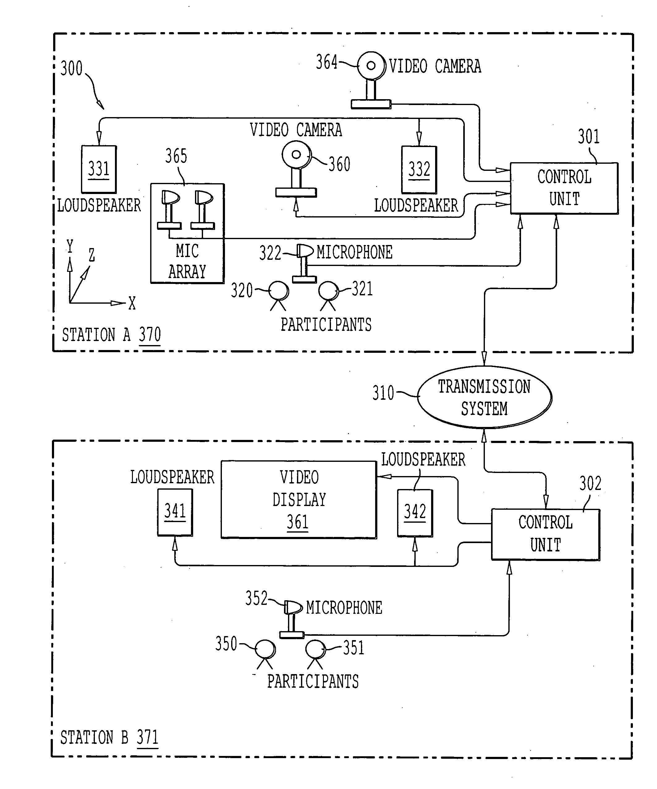
Referring now to the drawings, wherein like reference numerals designate identical or corresponding parts throughout the several views, and more particularly to FIG. 1 thereof, which illustrates one possible embodiment of the present invention. In FIG. 1, an arrangement used to localize the position of an audio source, participant 1, includes at least one microphone device 3 positioned separately from a camera 2. A distance “b” from the microphone device 3 to the participant 1 is less than a distance “a” from the microphone device 3 to the camera 2, thus allowing a more correct near field assumption.

A localization device, preferably placed as close to the camera in use as possible, locating one or more of the microphones, is preferably positioned as close to the participants as possible, while the microphone(s) (from now on referred to as table microphone) in turn localizes the audio source relative to their own position(s). The table microphone is provided with two or more micro...


PUM


Abstract

An arrangement and a method of localizing active speakers in a video conference includes a localization device that locates at least one microphone relative to the camera, while the at least one microphone in turn localizes the relative positions of audio sources. As the microphones are usually positioned close to the audio source in a video conference, the ratio of the distance between microphones relative to the distance between table microphone and audio source is reduced. Thus, the microphones are able to determine the positions of the audio sources with a higher resolution than if placed close to the camera. When the respective positions of the microphones relative to the camera and the audio source are known, the position of the audio source relative to the camera is then determined by means of geometrical calculations.

Description

BACKGROUND OF THE INVENTION 1. Field of the Invention The present invention relates to signal source localization, in particular an arrangement and method of spatially localizing active speakers in a video conference. 2. Discussion of the Background Signal localization is used in several applications. The most known application is perhaps TV program production. For example, in debate programs, it is important for the viewer's experience and intelligibility that the active camera is pointing at, and preferably zooming on, the current speaker. However, this has traditionally been handled manually by a producer. In other applications where cameras and microphones are capturing the view and sound of a number of people, it might be impossible or undesirable to have a dedicated person to control the performance. One example of such application is automatic camera pointing in video conferencing systems. A typical situation at an end-point in a video conference call is a meeting room w...

Claims


Application Information

Patent Timeline
IPC IPC(8): H04N7/15H04R27/00
CPCH04R27/00H04N7/15
Inventor MUREN, PETTERMARTON, TRYGVE FREDERIKJOHANSEN, TOM-IVAR
Owner CISCO TECH INC
Why Eureka
Try Eureka